What is an Analog Circuit?
In contrast to a digital circuit, which requires a signal to be one of two discrete levels, an Analog circuit uses a continuous, variable signal that is called an Analog signal. Changes in current, voltage, or frequency can be used to communicate information in Analog circuits. Resistors, capacitors, inductors, diodes, transistors, and operational amplifiers are all intrinsically Analog. Circuits that are made up entirely of these components are known as Analog circuits [1].
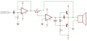 Figure 1: A simple Analog Circuit
Introduction to Filters
A filter or also known as a frequency selective circuit is a special type of circuit in Analog electronics, which is used for filtering out some of the input signals based on their frequencies. Depending on the filter type, a filter circuit allows some frequency range without attenuation or with slight amplification while attenuating others [2].
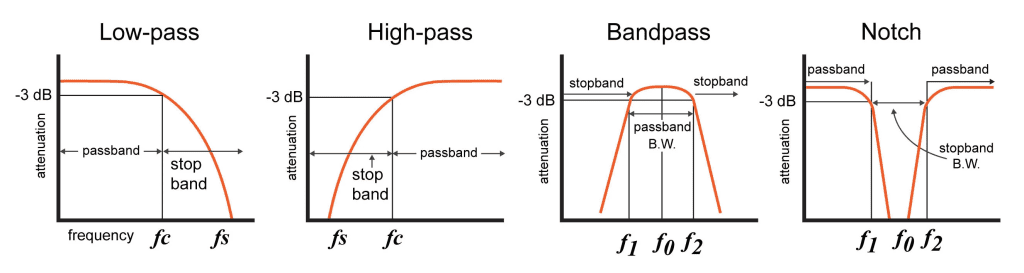
Generally, there are four types of frequency filters used to filter different portions of the frequency range
- Low pass filter
- High pass filter
- Bandpass filter
- Bandstop/notch filter
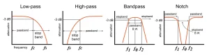
Figure 2: Types of frequency filters
Application of Filters
Filters are critical building elements of any Electronic and Communication System. A filter is a linear circuit that removes undesired components from an input signal by changing the amplitude and/or phase properties of a signal concerning frequency. Such as noise, interference, distortion, or any unwanted frequency span [3].
Among the applications are:
- Background noise is reduced using filter circuits.
- They’re used to tune a radio to a certain frequency.
- Used in audio systems for pre-amplification, equalization, and tone control.
- They’re also employed in data conversion and signal processing/conditioning circuits.
- Medical Electronic Systems make considerable use of filter circuits.
Passive and Active Filters
Passive filters are constructed out of passive components such as resistors, capacitors, and inductors, as the name implies. It does not require any external energy source. As a result, these filters do not have any voltage gain. The output voltage is never equal to the input voltage. Although its design is straightforward, adding a load to this filter has an influence on its performance [2].
An active filter includes an operational amplifier, transistors, and other active components in combination with the resistor and capacitor. The disadvantage is that it requires an external power supply, although it has a high voltage gain, and the input signals will be multiplied by this gain factor. They may have a more complicated design, but they have a very high input and low output impedance. As a result, the active filters’ properties are unaffected by the load impedance [2].
Terms Used in Filter Design
To comprehend a filter’s frequency response, you must first understand the terminology involved in it. The following are some of the terminologies used to describe the properties of a filter [2].
Passband
The Passband refers to the range of frequencies in the input signal that passes through the filter without being attenuated. If the filter is passive, the Passband usually has no gain. The passband of active filters may have some gain depending on the circuit setup.
Stopband
Stopband refers to the range of frequencies in the input signal that is blocked or dampened by the filter. Typically, the gain at the stop is less than -3db of the input.
Cut-off Frequency
The passband & stopband are distinguished from each other by the cut-off frequency or corner frequency. The output signal’s voltage at the cut-off frequency is 70.7% of the input signal’s voltage. It is also known as -3db frequency.
Centre Frequency F0
The centre frequency represents the midpoint frequency in between the -3dB cut-off frequencies of a bandpass or notch filter. The -3dB cut-off points are also referred to as the lower cut-off frequency and upper cut-off frequency of a filter circuit [4].
For wider bandpass filters where the ratio of f2/f1 is greater than equal to 1.1, the centre frequency can be approximated by the following formula.
F0 = √(f1 f2)
However, for narrowband bandpass filters where the ratio of f2/f1 is less than 1.1, the centre frequency can be calculated by the addition of the 2 cut-off frequencies divided by 2. This is shown in the formula
F0 = (f1 + f2) / 2
Bandwidth:
The bandwidth of a filter is the range of frequencies that flow through it without attenuation in the case of a bandpass filter or are attenuated in the case of a band-reject filter.
Β = f2 – f1
3 Ways to Design Analog Filters
In this article, we will discuss three alternate ways to design a bandpass filter with the following specifications.
- Lower cut-off frequency f1 = 1kHz
- Upper cut-off frequency f2 = 5kHz
- Gain = 1
- Order = 2
- Type: Butterworth
Filter design Software’s from Texas Instruments and Microchip can be helpful in this regard. Each software provides a graphical user interface that is very easy to use. In the end, we will have a look at how to design a band-pass filter by using mathematical equations.
1. Filter Lab Software by Microchip
Filter Lab is an innovative software tool that simplifies active filter design. Available at no cost from Microchip’s website https://www.microchip.com/en-us/development-tool/FilterLabDesignSoftware. Filter Lab active filter software design tool provides schematic diagrams of the filter circuit with recommended component values and displays the frequency response. Filter Lab allows the design of low pass filters up to an 8th order filter with Chebyshev, Bessel, or Butterworth responses from frequencies of 0.1 Hz to 1 MHz
Filter Lab also can be used to design band-pass and high-pass filters with Chebyshev and Butterworth responses up to 8th order. The downside is that in the filter lab the upper passband frequency to lower passband frequency ratio must be between 1.23 and 5.82. Moreover, a narrower passband cannot be designed in the current version of the filter lab.
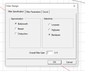
Figure 3: Filter specifications tab
The Filter Specification tab enables the user to specify the approximation type, the selectivity, and the gain. Select any approximation, in our case, it’s Butterworth with a gain of 1. The maximum allowed gain is 10 V/V.
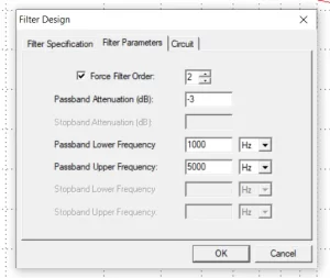
Figure 4: Filter parameters tab
After selecting the Butterworth approximation, bandpass filter option, and the gain of 1, enter the filter parameters in the filter parameter tab. Here the Force Filter Order option enables the user to specify the filter order or have the program calculate the filter order based on the dialog entries. When the checkbox is selected, the user specifies the Pass Band Attenuation and the Pass Band frequencies. Filter Lab then calculates the Stop Band Attenuation and Stop Band frequencies based on the order. When the checkbox is not selected, the user specifies the attenuation and all frequency values. Filter Lab then calculates the order based on the attenuation and frequency values.
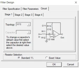
Figure 5: Circuit tab
The circuit topologies supported by Filter Lab are the Sallen Key and Multiple Feedback (MFB). In the circuit tab, the user can select the topology and the capacitor value for maximum design flexibility allowing real-world values to be substituted or changed as part of the design process. It is worth noting that Band-pass selectivity only supports Multiple Feedback (MFB) topologies, while the high-pass selectivity only supports Sallen Key topologies. Changing the topology only affects the stage for the active tab.
Once the filter response has been identified, Filter Lab generates the frequency response and the circuit. The frequency response graph is detailed however the user cannot change the type of sweep. Furthermore, the circuit is well constructed showing the values of the utilized resistor and capacitor, but the software gives no information/ specifications about the employed Operational Amplifier.
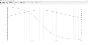
Figure 6: Frequency response
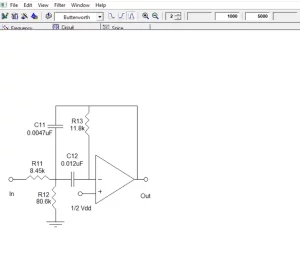
Figure 7: Circuit diagram
Filter Lab also generates a SPICE model of the designed filter. Extraction of this model will allow time domain analysis in SPICE simulations, streamlining the design process.
2. Filter Design Tool by Texas Instruments
The filter design tool lets you design, optimize, and simulate complete multi-stage active filter solutions within minutes. Is an extremely advanced and high-end tool with all sorts of options which makes filter designing much easier. The tool is available on the Texas instrument Website https://webench.ti.com/filter-design-tool/. The good thing about this tool is that it’s free, and no need to download any software as it can be used online on a web browser.
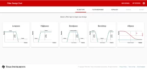
Figure 8: Filter type selection page
Users can make low-pass, High-pass, Bandpass, Bandstop, and All-pass filters without any resistance or limitations. After selecting the type of filter which is in our case bandpass the tab moves on to the Filter Response, where the user can enter the filter specifications and visualize the response of the filter.
Following are the calculations to calculate the centre frequency and bandwidth
Since 5000/1000 > 1.1
So,
Centre Freq Fc = √(1000 * 5000)
Centre Freq Fc = √(5000000)
Centre Freq Fc = 2236 Hz
Bandwidth = f2 – f1
Bandwidth = 5000 – 1000
Bandwidth = 4000 Hz
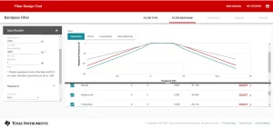
Figure 9: Filter response tab
Users can also navigate to view the phase, group delay, and step response graphs. A gain of 1000 could be achieved by this tool. The centre frequency and bandwidth ranges are from 0.1-10MHz and 0.1-1GHZ respectively, which is more than enough for most of the filter applications. This tool also gives users the privilege to set the response up to 20th order in all of the filter types with the auto feature. Furthermore, the following are 7 different filter responses that can be selected using this tool, each with its Quality factor Q.
- Bessel
- Butterworth
- Chebyshev
- Linear Phase 0.5
- Linear Phase 0.05
- Transitional Gaussian to 6 dB
- Transitional Gaussian to 12 dB
Depending on the application user can select any of the filter responses and move to the topology tab.
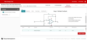
Figure 10: Topology tab
In the topology tab, the topologies supported by the Filter design tool are the Sallen Key and Multiple Feedback. Different topologies for different stages can also be selected. A short description of the order, gain, and components can also be seen in this tab. Now clicking the create design button will create a complete design of the filter.
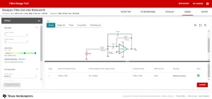 Figure 11: Design tab
In the design, tab user can view the complete circuit. The exceptional thing about this filter design tool is that it will also select an appropriate Op-Amp based on the Gain Bandwidth GBW and supply voltage along with the resistor and capacitor values. It also calculates the required GBW, and it gives the option to choose an alternate Op-Amp by either changing the GBW value or directly selecting an Op-Amp by clicking on Choose Alternate OP Amp button. Also, users can even select the tolerance of the components to reduce the variance in filter performance. Clicking on the export button will export the data of all tabs.
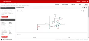 Figure 12: Export tab
In this tab, the user can fully visualize the circuit and the charts like Magnitude, Phase, Group Delay, and Phase response, or click on the print report option to generate a complete design PDF. Moreover, you can export your design to get a simulate able schematic file. You will need to download and install TINA-TI first to open and simulate the exported design in TINA-TI to further verify and test the filter performance. A full electrical bill of the material comes in handy when it comes to the component’s information and usage. The ordering option of all the components at this stage is also a great plus.
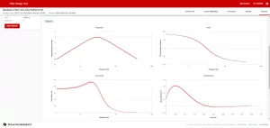
Figure 13: Response charts
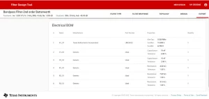
Figure 14: Electrical BOM
3. Using Mathematical Equations
A bandpass filter is a combination of low pass and high pass filters. The first half of the circuit is a passive RC high pass filter, and the second half of the circuit is a passive RC low pass filter. A high pass filter will allow the signals which have frequencies higher than the lower cut-off frequency (FC-low). And attenuate the signals which have frequencies lower than (FC-low).
FC-low = 1/(2πRC)
On the other hand, the RC low pass filter will allow the signals which have frequencies lower than the higher cut-off frequency (Fc-high). And it will attenuate the signals which have frequencies higher than (FC-high).
FC-high = 1/(2πRC)
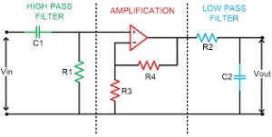 Figure 15: Bandpass Filter
Example: Active Bandpass Filter Circuit Design
To design a bandpass filter, we have to calculate the values of capacitor C1 and resistor R1 of the High pass filter by using the following formula.
FC-low = 1/(2ΠRC)
Let R1 = 1.5k
1000 = 1/ (2 x π x 1500 x C)
C1= 100nF
Now by using the formula of FC-high we can calculate capacitor C1 and resistor R2 of the low pass filter
FC-high = 1/(2πRC)
Let R2 = 6.8k
5000 = 1/ (2 x π x 6800 x C)
C2= 4.7nF
Since the gain of 1 is required, we could just connect the inverting input to the output of the Op-Amp and thus make it a voltage follower. Now to confirm the functionality of the circuit is simulated in the LTspice simulation software. The following circuit has been constructed and simulated in the software.
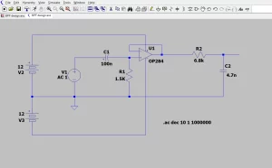
Figure 16: Circuit Design in LTspice
The frequency response graph illustrates 2 plots one is the magnitude, and the other is a phase. It can be observed that the -3dB lower cut-off is exactly at 1Khz and the -3dB upper cut-off is also precisely at 5Khz. Thus, it is clear that the filter is working perfectly as a bandpass filter.
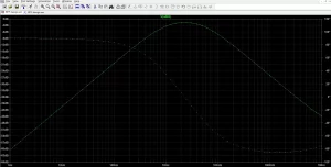
Figure 17: LTspice Frequency Response
Conclusion
As discussed above the three different ways to design a bandpass filter. Understandably, the software makes the life of a designer much easier and the design process much simpler when it comes to Analog filter design. On the other hand, filters can also be constructed by solving complex mathematical equations, which is a time-consuming and intricate approach. Moreover, to verify the working of the designed filter, simulation of the circuit is also mandatory by using simulation software. In contrast, if you want a quick design and characteristic charts by entering the desired specification then filter design software is your best bet.
Software from Microchip has some limitations and cannot go beyond the 8th order filter. Also, the frequency range can only be set according to a fixed ratio. Texas instruments software on the other hand can allow filter design up to 20th order. In general, the filter design tool from Texas Instruments provides tons of more options, it’s very descriptive with an easy-to-use user interface when compared with microchip’s Filter Lab.
References
| [1] | JIMBLOM, “Analog and Digital Circuits,” [Online]. Available: https://learn.sparkfun.com/tutorials/analog-vs-digital/analog-and-digital-circuits. |
| [2] | E. Technology, “Filters, Types of Filters and Their Applications,” [Online]. Available: https://www.electricaltechnology.org/2019/06/types-of-filters.html. |
| [3] | L. Ashrit, “Filters – Classification, Characteristics, Types, Applications & Advantages,” [Online]. Available: https://electricalfundablog.com/filters-classification-characteristics/. |
| [4] | L. a. Electronics, “Center Frequency Calculator,” [Online]. Available: http://www.learningaboutelectronics.com/Articles/Center-frequency-calculator.php#answer. |
If you want to discuss any design related problem on the subject of Analog Filters, or any other Hardware Design related challenge in general, feel free to Contact Us for our consultancy. You can check out our other Technical Blogs on various topics or visit our new website Oxeltech.de to find all about our services and products.