
What is USB Type-C?
USB Type-C is a connector specification developed by USB Implementers Forum (USB-IF). It is not a communication protocol such as USB 3.2 and USB 2.0. The “C” designation signifies its unique physical form factor, distinct from earlier USB connectors.
 One of its hallmark features is its reversible design, which eliminates the need to distinguish between host and peripheral ends. This ensures effortless connections every time.
USB-C Lanes & Speed
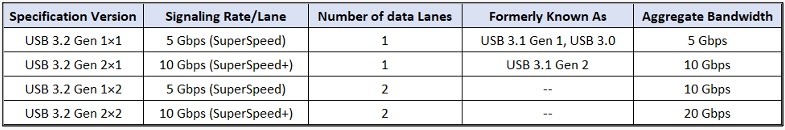
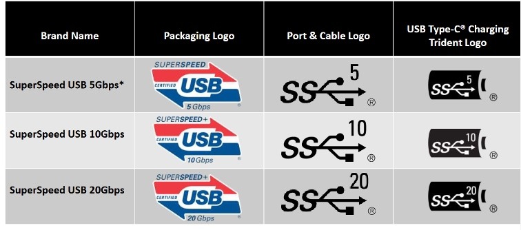
USB Type-C offers impressive data transfer speeds. It adheres to USB 3.2 standards, supporting SuperSpeed USB 10Gbps and SuperSpeed USB 20Gbps modes.
The USB 3.2 specification encompasses all previous iterations of the USB 3.x standards. It categorizes transfer rates into three distinct levels: USB 3.2 Gen1 (5Gbps), USB 3.2 Gen2 (10Gbps), and USB 3.2 Gen2x2 (20Gbps).

The naming convention recently adopted for USB 3.2 is interpreted as “speed x lanes”. For example, USB 3.2 Gen 1×2 means 5 Gbps x 2 lanes, for a connection speed of 10 Gbps.
 Source: USB Implementers Forum © 2019 – Branding Presentation
What are some key features & benefits of the USB Type-C?
Reversible Connector
This is one of the most notable features of USB-C. It is a reversible connector and can be flipped/inserted either way relative to the receptacle, unlike the older connectors which had to be inserted in a specific orientation.
High Speed
It can support all current generations of USB i.e., USB 2.0 High Speed (480 Mbps) and USB 3.2 Super Speed (5 Gbps, 10 Gbps & 20 Gbps).
Supports Third-Party Protocols
It can support third-party protocols such as DisplayPort and HDMI in a mode of operation called Alternate Mode.
Up to 240W of Power
The standard allows the devices to negotiate and choose an appropriate level of power flow through the interface. This means USB-C can charge and/or drive a wide range of devices and can deliver up to 240 Watts of power!
Compatibility with Older USB Standards
USB-C is backward compatible with older USB standards using adapters or cables. This means that USB-C devices can connect to older USB-A or USB-B ports with the appropriate accessories.
Enhanced Durability
USB-C connectors are designed to be more durable than previous USB connectors. The connector is designed to withstand more plugging and unplugging cycles when compared to other connectors.
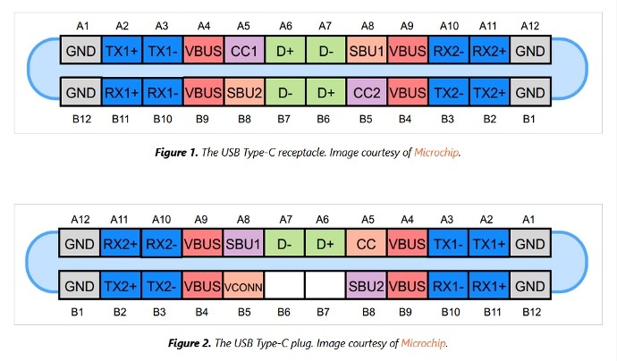
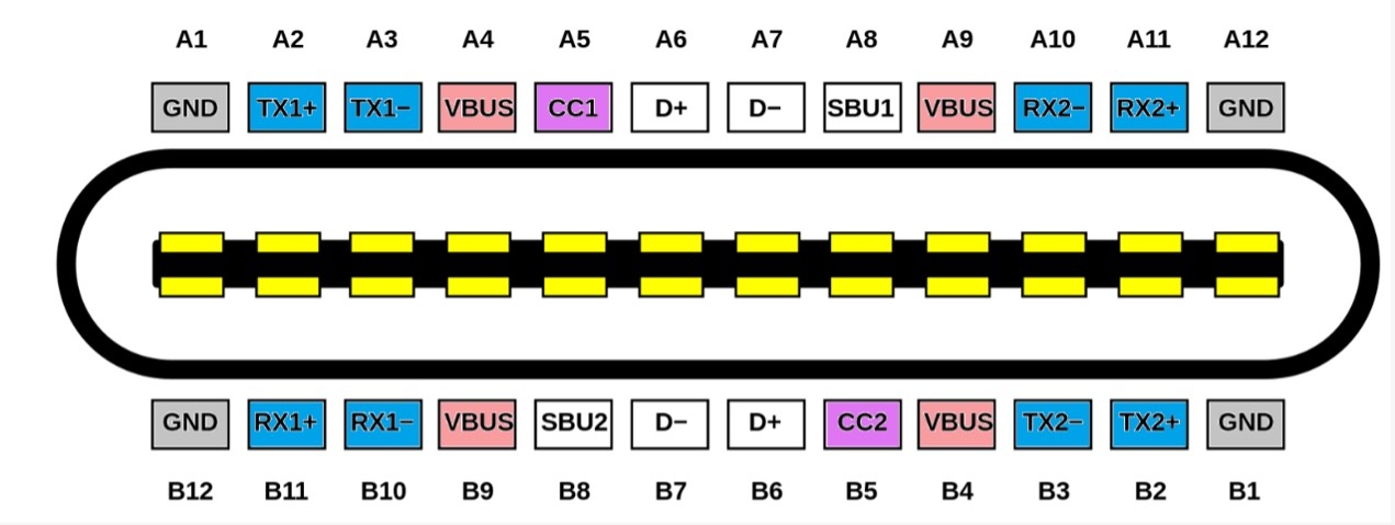
USB TYPE-C Pin Description
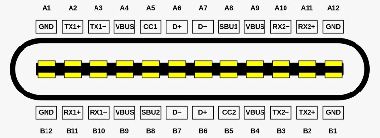
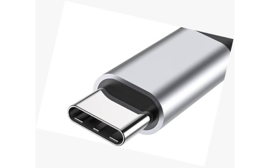
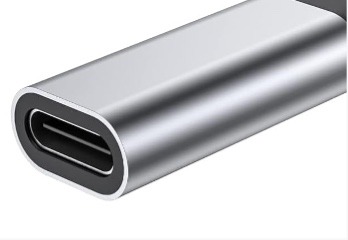
USB-C Connector / Receptacle Pinout – (Image Courtesy of Wikipedia)
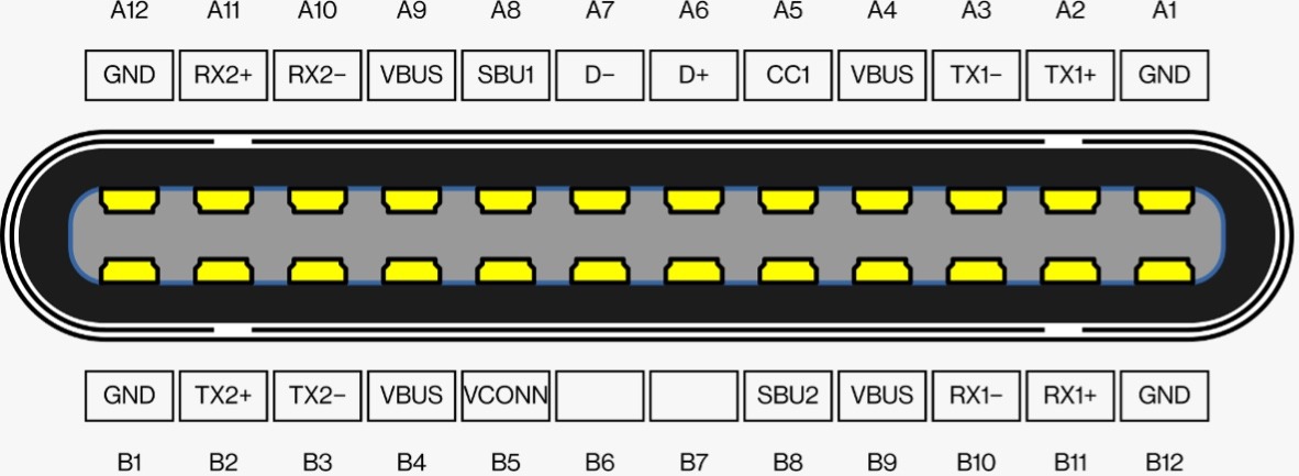
USB-C Plug Pinout (Image Courtesy of Wikipedia)
- USB 2.0 Differential Pairs: D−, D+
- Two lanes/sets of USB 3.x Differential Pairs : TX1−, TX1+, RX1−, RX1+ & TX2−, TX2+, RX2−, RX2+
- CC1 and CC2 Pins: Used for cable orientation detection, USB Type-C current advertisement and detection
- SBU1 and SBU2 (Auxiliary Signal Pins): Lower-speed signal wires that are allocated for Alternate Mode use
- VBUS and GND: These pins are for USB cable bus power and the current return path.
- VCONN: The unused CC pin on plug is used to apply power to the local plug and is referred to as VCONN
USB TYPE-C Usage Possibilities
Use as USB2.0
The USB-C can be used for the default Low/Full/High-Speed (2.0) connection – using the default D+ and D- pair for the data signal.
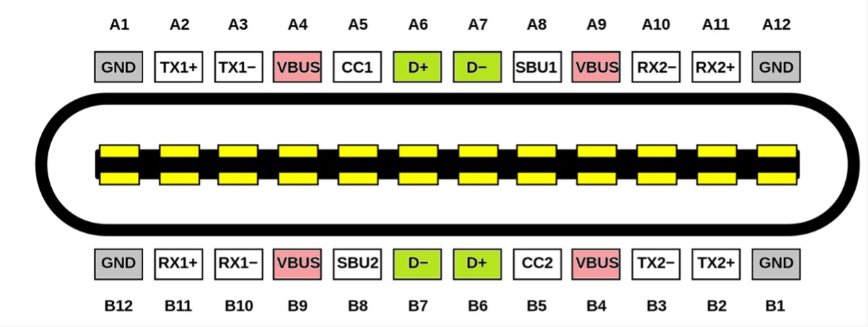
Use as USB3.0
It can also be used for SuperSpeed (3.x) connection – using the high-speed lanes and configuration control pins. Two pair of pins are defined to enable dual-lane operation.
Use for Power Delivery
There’s also the possibility to use it as a Power Delivery interface (Charger), where VBUS, GND, & Configuration controls (CC) are used. USB-C can charge or drive a wide range of devices and can deliver up to 240 Watts of power!
Use in Alternate Mode (such as DisplayPort)
In Alternate Mode, it can function as a DisplayPort, for instance. Utilizing up to 4 data lines involves repurposing the superspeed lane as display port signals and utilizing the SBU as an auxiliary channel for configuring the displays.
It can be used as an Audio Adapter Accessory, which means it can transmit audio data directly in digital form from the device to the headphones or external speakers.
You may ask, how it detects the right configuration. The answer is CC pins. The Configuration Chanel CC pins serve to detect connections, cable/plug orientation and configure the interface across USB Type-C cables and connectors.
“Host” and “Device” Have Been Renamed in USB-C
Let’s look at some of the new terms introduced in USB-C and how it relates to the older standard:
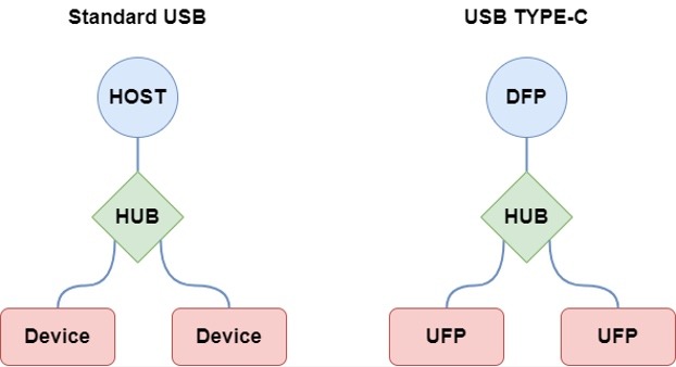
The USB Type-C specifications have introduced updated terminology, replacing the traditional terms “host” and “device” with “Downstream Facing Port (DFP)” and “Upstream Facing Port (UFP)” respectively. This change in naming reflects the adaptable nature of Type-C, allowing for the interchangeability of these components’ roles as required.
- DFP: Downstream Facing Port – A USB port functioning as a host and power source.
- UFP: Upstream Facing Port – A USB port serving as a client and power sink.
- DRD: Dual Role Device – Capable of functioning as either a host or client, replacing the term “OTG.”
- DRP: Dual Role Power – Able to operate as either a power provider or power consumer.
The DRD and DRP terms in the USB-C standard are intentionally created. These terms were introduced to categorize devices based on two distinct roles:
- Data direction, distinguishing between hosts and clients.
- Power direction, distinguishing between power sinks and power sources.
This classification allows for devices to simultaneously serve as clients in terms of data direction and as power sources in terms of power direction. A prime example of this functionality can be found in certain docking stations, which function as USB clients while also serving as the power source for charging a laptop.
Configuration Channel (CC pins)- What Do They Do?
CC1 and CC2 pins in USB-C have three key functions:
- Detecting cable orientation for proper communication.
- Identifying device roles to prevent damage and define communication hierarchy.
- Negotiating power configurations between client and host devices for optimal power distribution.
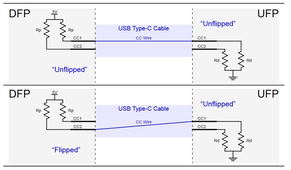 Cable orientation and role detection – Image courtesy: Microchip
- In the upstream devices, there are pull-down resistors in CC1 and CC2 pins.
- In the downstream devices, there are pull-up resistors in CC1 and CC2 pins.
- In passive cables, there is only one routed CC pin pair.
By detecting voltage changes in CC1 and CC2 pins, each side can efficiently determine various parameters. More importantly, some USB devices handle all CC mode settings, so you should understand what chip you are integrating and see if it is capable of assigning roles using the CC1 and CC2 pins:
- Role detection: A voltage change signifies UFP or DFP presence. Absence of voltage change indicates absence of corresponding device type.
- Cable orientation: Identifying which pin experiences a voltage change reveals cable orientation at each end.
- Power detection: The voltage level, influenced by pull-up resistor values, allows the DFP device to communicate its power delivery capability to the UFP device.
Power Delivery Chart – USB-C
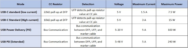
USB Type-C Power
All solutions required to support Default USB Power appropriate to product – as Defined by USB 2.0, USB 3.2 and USB4™ (as defined in the USB Type-C spec)
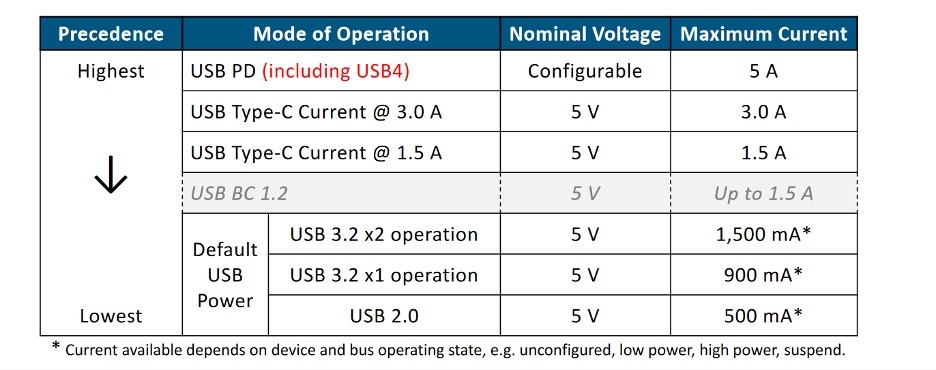
Power Delivery & Precedence (Image courtesy: USB IF)
Summary
USB-C represents a significant advancement in USB technology, combining data transfer, power delivery, and video output capabilities in a single connector with a reversible design. USB 3.2 offers impressive data transfer rates up to 20 Gbps and USB-C has an ability to deliver up to 240 Watts of power through USB Power Delivery.
Additionally, USB-C’s support for Alternate Modes enables functionalities like DisplayPort and HDMI. USB-C’s design also ensures enhanced durability and backwards compatibility, making it a forward-thinking solution for both current and future technological needs. And unlike USB-A you don’t have to try inserting it 3 times, before getting the right orientation 😉
References:
-
- Official USB Specification
https://www.usb.org/documents
https://www.usb.org/document-library/usb-type-cr-cable-and-connector-specification-release-23
https://www.usb.org/document-library/usb-type-cr-locking-connector-specification
https://www.usb.org/document-library/usb-type-cr-system-overview
https://www.usb.org/document-library/usb-branding-session - Wikipedia
https://en.wikipedia.org/wiki/USB-C - Microchip App notes & Articles
Introduction to USB TYPE-C: https://ww1.microchip.com/downloads/en/appnotes/00001953a.pdf
https://microchipdeveloper.com/usb:type-c - Other Resources:
https://www.allaboutcircuits.com/technical-articles/introduction-to-usb-type-c-which-pins-power-delivery-data-transfer/
- Official USB Specification
Facing challenges with USB-C or USB 3.x interface design, PCB layout, or electronic product development in general? Feel free to Contact Us for embedded architecture, hardware interface design, and firmware implementation services.