
Project overview:
A German medical-device manufacturer required an audio-to-laser modulation system for a therapeutic laser device. Some patients report calming effects when laser brightness varies in sync with audio, but the client had been unable to achieve this reliably after three failed PCB iterations using digital signal processing (DSP).
Oxeltech was brought in to identify the root cause and deliver a working design. The system converts stereo audio signals into real-time laser-brightness modulation.
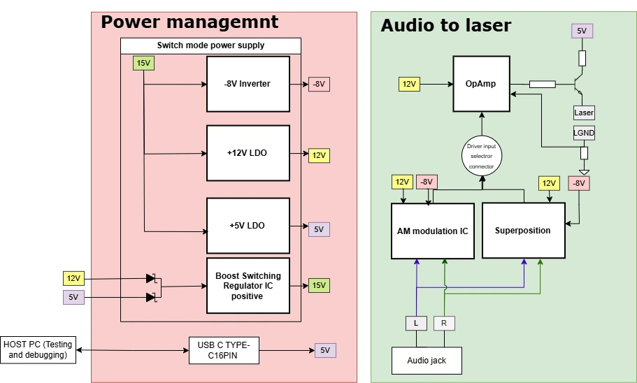
Figure 1: Block Diagram of the Audio-Driven Laser Therapy Control System
Constraints and challenges:
Power limits: System operates at USB (5V) and (12V) DC adapter supply.
Size target: The PCB had to fit within a 50mm × 60mm area, and the existing footprint and connector positions had to be retained.
Audio input: 170–200mV from a 3.5mm jack with an unclear specification (RMS vs peak). Required bandwidth was 20Hz to 20kHz, with a future target of 100kHz.
Laser safety: Maximum output power of Class 1 (1 mW) per DIN EN 60825-1 (German laser safety regulations).
Legacy issues: Poorly documented schematics and unknown behavior of the existing laser module with internal driver electronics.
Technical decisions:
DSP approach failure: Digital pulse width modulation (PWM) switching created gaps in the output waveform. The laser turned on and off rapidly rather than varying its brightness smoothly. This caused a visible flicker and failed to deliver the continuous current control required for therapeutic use. As a result, we shifted to analog signal processing (ASP) and evaluated two alternative solutions.
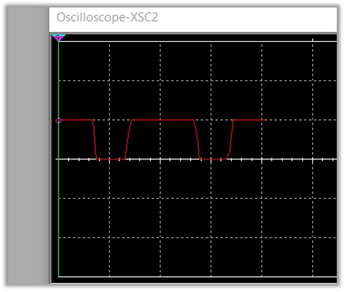
Figure 2: PWM switching gaps causing laser flicker
Amplitude modulation: We used a balanced modulator IC to replace the entire DSP signal chain. This IC performs analog multiplication, enabling true amplitude modulation without switching artifacts. It supports linear operation with 100 MHz bandwidth, eliminates analog-to-digital and digital-to-analog conversion delays, and requires no firmware.
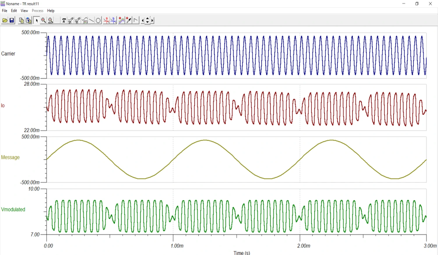
Figure 3: AM output via balanced modulator IC
Superposition: The op-amp performs signal superposition by summing the audio signal and applying variable gain via a potentiometer-based feedback network. This accommodates uncertain input levels (RMS vs peak ambiguity).
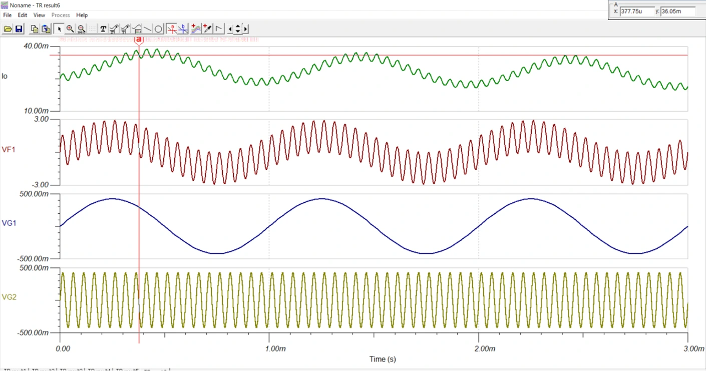
Figure 4: Op-amp summing audio signal with variable gain
Laser driver: We used a Howland current pump with a rail-to-rail op-amp to maintain a stable bias current with ±2mA modulation superimposed. This ensures a linear laser-brightness response across the full audio-frequency range.
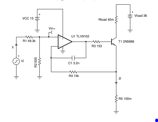
Figure 5: Howland current pump circuit with rail-to-rail op-amp
Power management: To cater to a wide input voltage, we used a variable-voltage regulator with a range of 4V to 13V.
Implementation:
Test-driven validation: Injected test signals (100mV at 10 –100kHz carrier, 100mV at 1kHz modulation) to verify superposition behavior before finalizing gain stages.
Adjustable gain: Non-inverting summing configuration with a potentiometer allows field adjustment for varying audio sources.
Driver input selector: Allows selection between analog signal processing configurations depending on the application requirements.
Safety compliance: Current limiting maintains 5mW laser output maximum as required by DIN EN 60825-1 (German laser safety regulations).
Safety compliance: Current limiting maintains 5mW laser output maximum as required by German regulations.
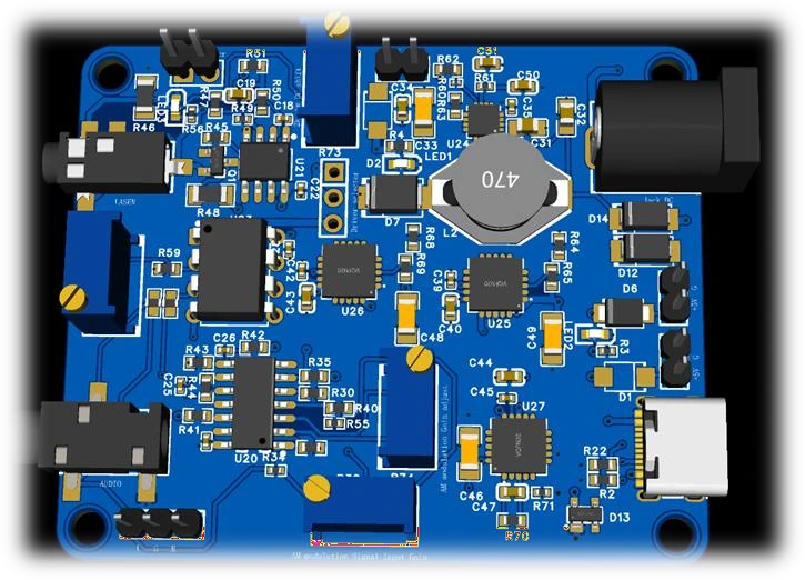
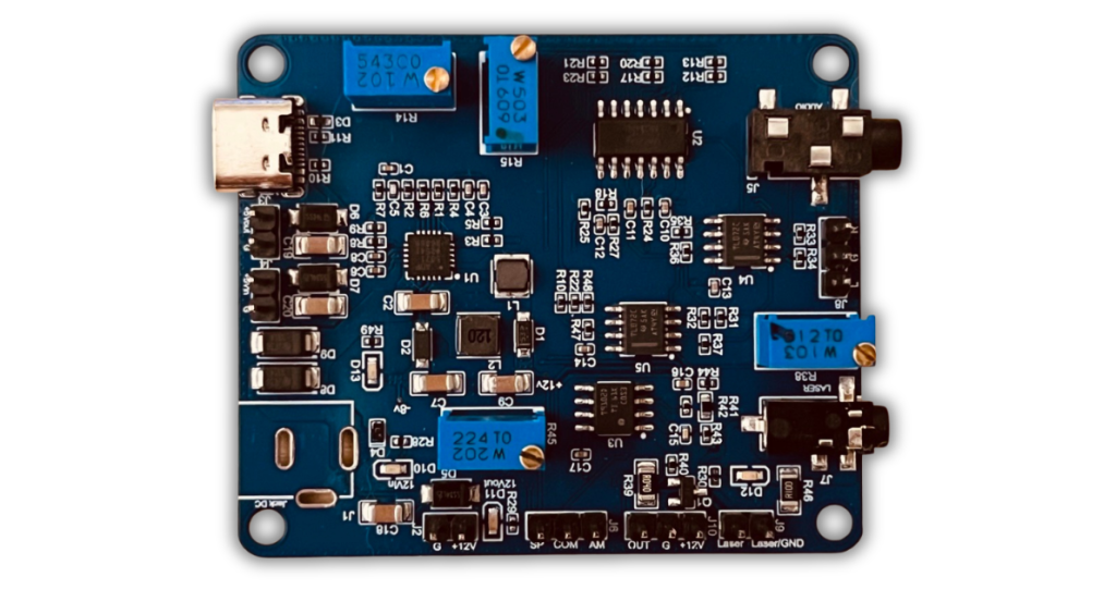
Figure 6: 3D View of the Audio-Controlled Laser Driver Board
Results and impact:
PCB size: Achieved a 50mm × 60mm board that fits the existing mechanical constraints.
Functionality: Delivered the first working iteration after three failed DSP attempts, with analog modulation and no visible flicker or gaps.
Bandwidth: Verified operation from 20Hz to 100kHz. The architecture supports extension beyond 100kHz without redesign.
Signal handling: Successfully modulated the laser using 170–200mV audio inputs.
Cost: Lower bill of materials (BOM) than the DSP approach, with no microcontroller, ADC/DAC, or firmware development required.
Limitations: Manual gain adjustment is required for different audio sources. There is no digital control interface.
Key takeaways:
- Analog signal processing solved a real-time modulation problem where DSP introduced latency and switching artifacts.
- Adjustable gain stages compensated for ambiguous audio specifications without requiring multiple hardware revisions.
- Wide-input power management operating from 4V to 13V eliminated uncertainty about field power sources.
- Test signal injection during development verified modulation behavior before finalizing the design.
Summary:
Industry: Medical devices (therapeutic laser systems), Laser Applications
Core problem: DSP-based PWM caused flickering laser output instead of smooth brightness modulation for therapy.
Solution: Analog signal processing with adjustable signal conditioning
Key technologies: Balanced modulator IC, Howland current pump, rail-to-rail op-amp, potentiometer-based gain control.
Results: First working design after three failed iterations, 50mm × 60mm PCB, 20Hz–100kHz bandwidth, 5mW safety-compliant laser output, lower cost than the DSP approach.
FAQ:
Why ASP instead of DSP for audio modulation?
DSP requires ADC sampling, processing, and DAC reconstruction. At audio frequencies with PWM output, this creates discrete on/off switching. The laser flickers visibly instead of dimming smoothly. Analog signal processing produces continuous current control with no gaps in the waveform.
How was the uncertain audio input level handled?
We used a two-stage approach with adjustable gain. The first stage uses an op-amp with a potentiometer in the feedback path. This allows field adjustment from 170mV to higher levels without redesign.
How was the 5 mW laser safety limit enforced?
We implemented a constant current driver with drift compensation, setting the bias point at 25mA with a modulated swing of +-2mA. This set point could be varied by modifying the reference for both DC/AC setpoints, ensuring laser Class 1/Class 2 compliance.
If you’re developing a medical device with analog signal processing challenges, we’d be happy to help. Feel free to Contact Us for analog hardware design, PCB layout, and medical compliance services.