
Problem Statement
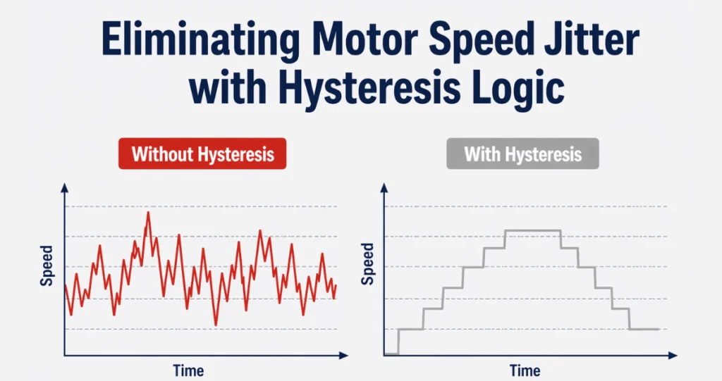
In motor control systems where speed is derived from an analog input (such as a potentiometer), small fluctuations in the input signal can cause frequent and unwanted speed changes. This leads to:
- Speed jitter
- Unstable user experience
- Excessive control updates
- Mechanical stress due to rapid small adjustments
To address this, hysteresis logic is introduced into the control system.
1. What is Hysteresis in This Context?
Hysteresis is a control technique used to prevent frequent switching caused by small input variations around a threshold.
Instead of allowing speed to change continuously with every small input variation, the system:
- Locks the output to discrete steps (for example, multiples of 5 RPM), and
- Allows changes only when the input crosses a defined boundary.
This creates a stable control region where minor signal noise or hand movement no longer affects motor speed.
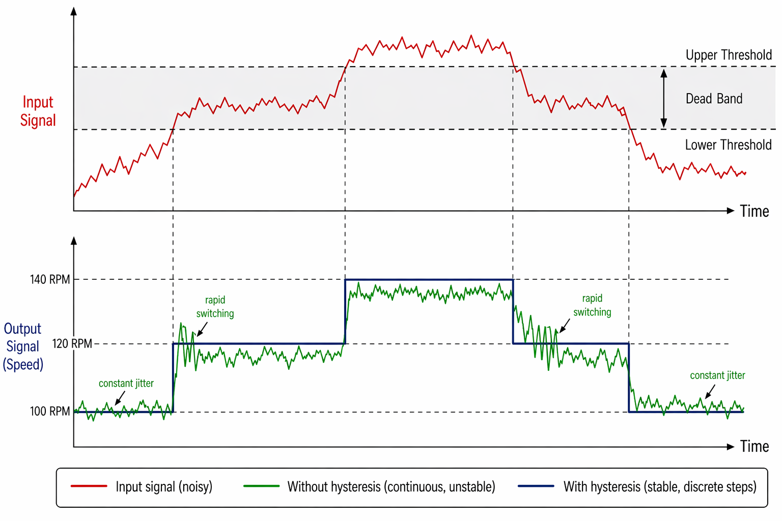
Figure: Hysteresis dead band controlling motor speed steps
2. Technical Overview of Implementation
The implementation uses a step quantization method with hysteresis locking.
Method Used: Step Quantization with Lock Flag
The system locks to the current value, subject to a minimum step size. If the minimum step is 1, all values are settable until the lock condition is activated.
Example:
- Raw speed = 137 RPM
- Locked speed = 135 RPM (nearest multiple of 5)
The system maintains this locked value until an unlock condition is met.
This approach provides:
- Stable output
- Reduced update frequency
- Predictable speed transitions
The logic is lightweight and well-suited for embedded systems operating under real-time constraints.
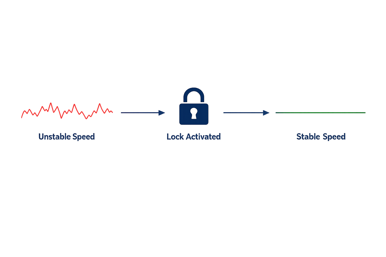
Figure: Unstable speed becomes stable once lock is activated
3. Lock Condition: Why It Is Necessary
The lock condition defines when hysteresis should be active.
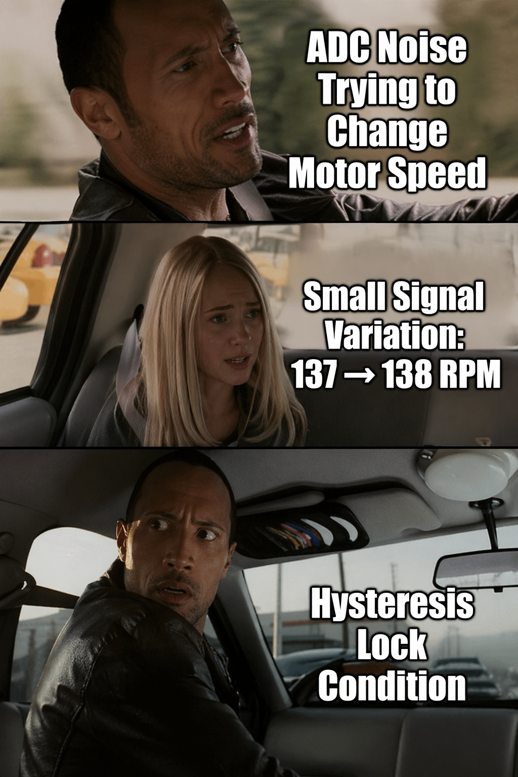
Without a lock condition:
- The system continuously reacts to small signal changes.
- ADC noise or minor user movement causes oscillations.
- Speed appears unstable even though the input change is minimal.
The lock condition ensures that:
- Once a speed step is selected, it remains stable.
- Small variations do not immediately affect output.
In this motor control implementation, the lock condition is enabled during normal operation to maintain smooth speed behavior.
4. Unlock Condition: Why and When to Unlock
While locking stabilizes the system, unlocking must be possible when the user intends to change speed significantly.
Unlocking allows the system to return to fine-grained control mode temporarily. It will still allow continuous change, as when we unlock it, we can select any value.
Typical reasons to unlock include:
- A large input change indicating an intentional adjustment
- Time-based inactivity timeout
- A button press or mode change
- Crossing a defined threshold boundary
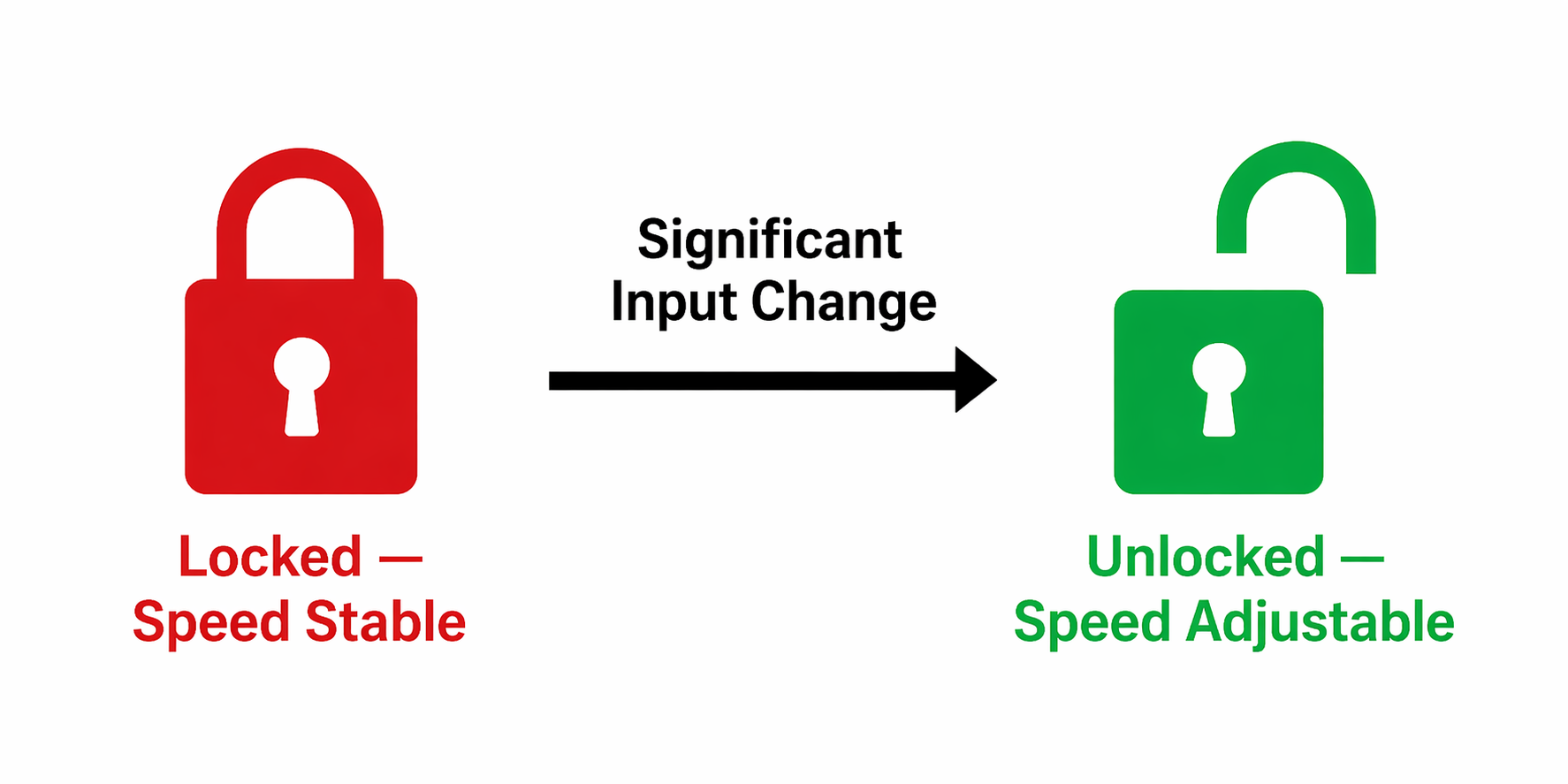
Figure: Significant input change unlocks the speed control
5. Overview of Common Unlock Methods
Several unlock methods can be used, depending on the system requirements:
a) Threshold-Based Unlock
The system unlocks when the input change exceeds a predefined delta value.
Use case: Quick response to intentional speed changes.
b) Time-Based Unlock
The system unlocks after a defined period of continuous input movement.
Use case: Prevents accidental unlock due to noise.
c) Event-Based Unlock
Unlocking is triggered by a user action such as a button press or mode change.
Use case: Systems with manual control modes.
d) Hybrid Method (Used in This Project)
A combination of step locking and input change monitoring is used to balance stability and responsiveness.
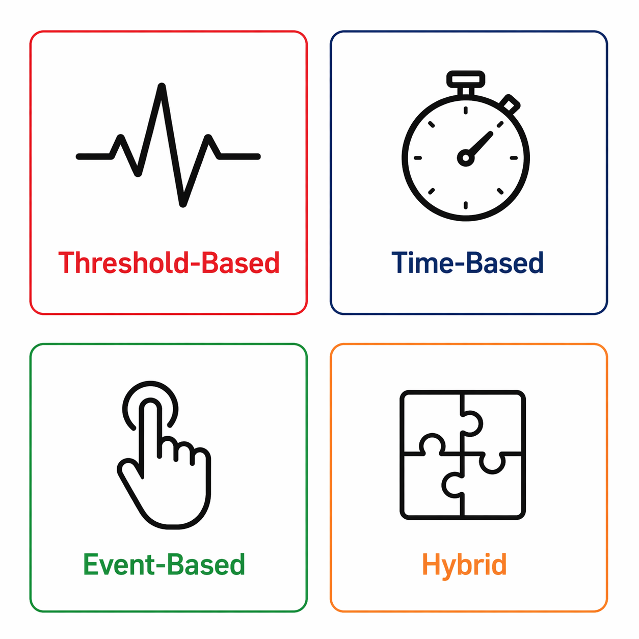
Figure: Four unlock methods, each suited for different system requirements
6. Resulting System Behavior
After introducing hysteresis logic with controlled unlocking, the system demonstrated the following behavior:
- Motor speed transitions became smoother and more predictable.
- Small input noise no longer affects the output signal.
- User control becomes stable yet responsive, improving the overall experience.
- Overall control loop activity is significantly reduced, lowering processing overhead.
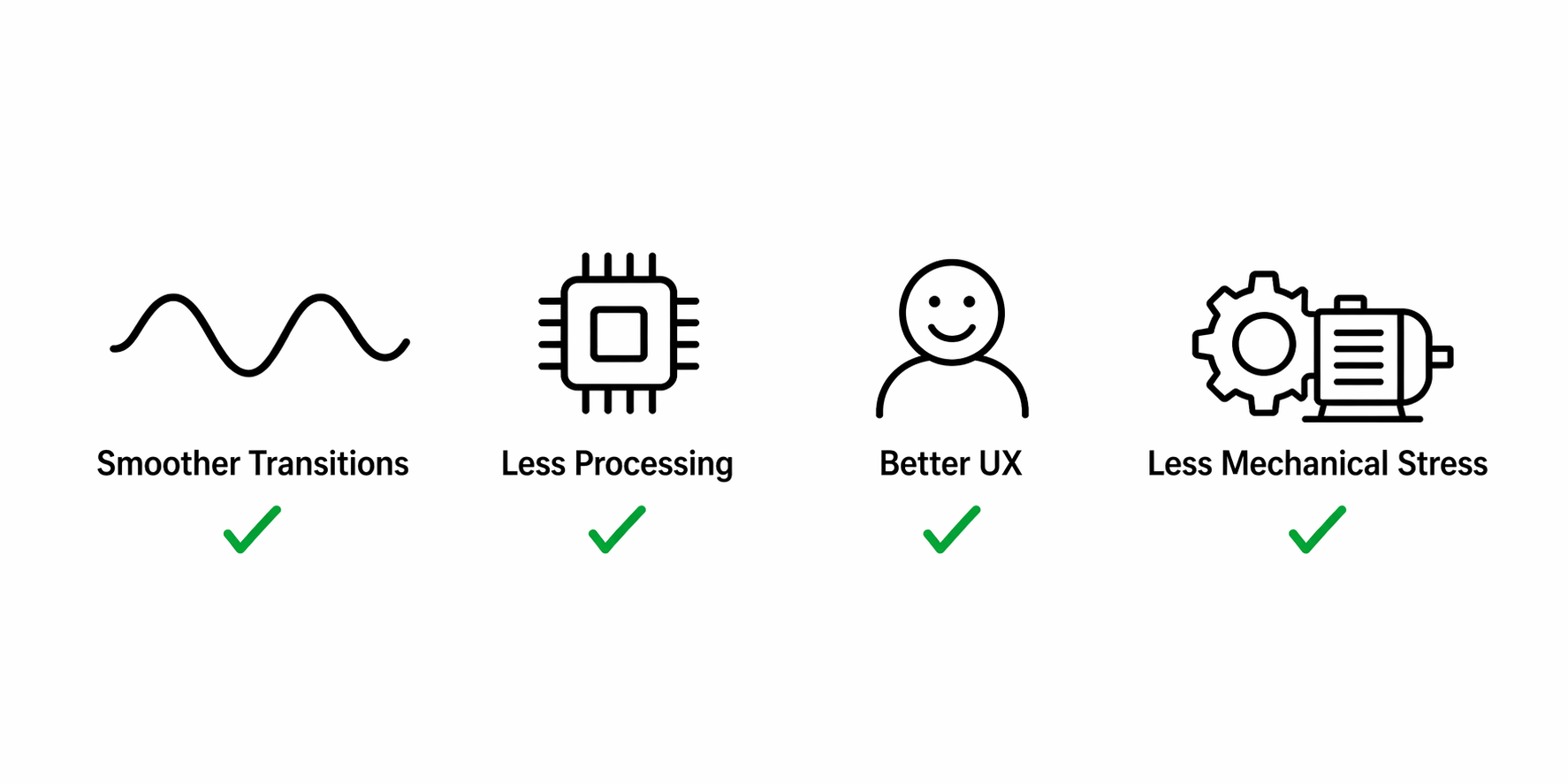
Figure: Key benefits after implementing hysteresis logic
Facing challenges with motor control or jitter in your embedded design? Feel free to Contact Us for PCB design, firmware engineering, and product development services.