The Core Challenge
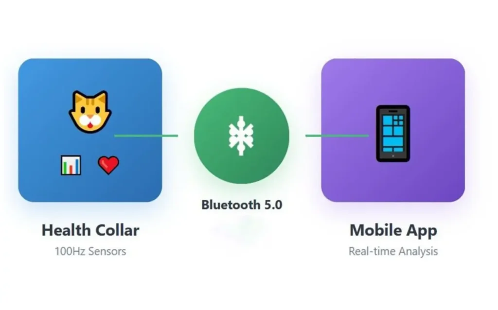
Building a dog health collar that streams 100Hz IMU and piezo sensor data over BLE sounds simple until you face the real problems:
- How do you timestamp 100 samples per second accurately?
- How do you handle BLE callbacks without blocking sensor readings?
- What happens when BLE connection and sensor callbacks try to access the same buffer?
- How do you keep the watchdog happy during slow BLE operations?
This post focuses on the data structures and BLE architecture we built to solve these problems.
Timestamp Strategy: Finding the Right Balance
The Problem with Timestamps
At 100Hz, we’re taking a reading every 10ms. Sending a full timestamp with every sample wastes bandwidth:
- 32-bit timestamp: 4 bytes per sample
- 100 samples/second × 4 bytes = 400 bytes/second just for timestamps
- Over two sensors, that’s 800 bytes/second of overhead
Our Solution: Testing Different Timestamp Approaches
We tested three different approaches:
Approach 1 – Every sample with absolute timestamp:
- Ideally BLE MTU size is kept <= 240 bytes
- Each BLE payload carries 15 samples of IMU data, i.e. 15 IMU samples x 12 bytes per sample = 180 bytes
- 4 bytes per sample for timestamp × 15 samples = 60 bytes just for timestamps
- Accurate but wastes bandwidth
Approach 2 – Every sample with relative timestamp (What we used):
- 2 bytes per sample × 15 samples = 30 bytes for timestamps
- We needed proof that each individual reading was captured at exactly 100Hz
- Having a timestamp on every sample gave us this verification
- Better bandwidth than approach 1
Approach 3 – First and Last timestamps only (Better for bandwidth):
- First Sample: Absolute timestamp (4 bytes)
- Last Sample: Absolute timestamp (4 bytes)
- Total: Only 8 bytes for entire packet
- Proof that 100Hz timing was maintained overall (verify duration between first and last)
- Phone can calculate middle timestamps by interpolating
- Saves 22 bytes per packet compared to approach 2
For our case, we used approach 2 because we needed proof of each reading being at 100Hz. Overall, approach 3 is better for bandwidth if you can accept interpolated timestamps for middle samples as we are estimating the time for each reading which may not be true.
Actual Packet Structure
IMU Packet (228 bytes):
Bytes 0-1: Packet Type (0x1001)
Bytes 2-17: Device ID (16 bytes)
Each of 15 samples (14 bytes per sample):
– Relative timestamp: 2 bytes (milliseconds offset)
– ax, ay, az: 6 bytes
– gx, gy, gz: 6 bytes
Piezo Packet (218 bytes):
Bytes 0-1: Packet Type (0x3001)
Bytes 2-17: Device ID (16 bytes)
Byte 18: Strip ID
Each of 20 samples (10 bytes per sample):
– Relative timestamp: 2 bytes (milliseconds offset)
– Raw ADC_1: 2 bytes
– Voltage_1: 2 bytes (mV)
– Raw ADC_2: 2 bytes
– Voltage_2: 2 bytes (mV)
The Callback Problem: BLE vs Sensor Interrupts
Initial Naive Approach (Failed)
Our first attempt was simple: sensor callback writes to buffer, BLE callback sends the buffer.
This failed immediately because:
- BLE callback could fire while sensor callback was writing
- Sensor callback could overflow buffer if BLE was slow
- No way to stop sensor reading during BLE connection process
The BLE Connection Process Problem
During BLE connection setup, the process can take 200-500ms. During this time:
- Sensor callbacks keep firing at 100Hz
- BLE stack is busy, can’t accept data
- Buffer fills up quickly (50 samples in 500ms)
- We needed to pause sensor callbacks but couldn’t lose timing accuracy
Our solution: Stop sensor callbacks during BLE connection to avoid buffer overflow and race conditions during the connection process. We also had to disable the watchdog timer during connection because it can take more than our normal 5-second timeout in poor signal conditions.
Stopping callbacks during connection means we lose a few hundred milliseconds of data, but we gain:
- Clean connection without buffer overflow
- Synchronized starting point with phone
- No race conditions during setup
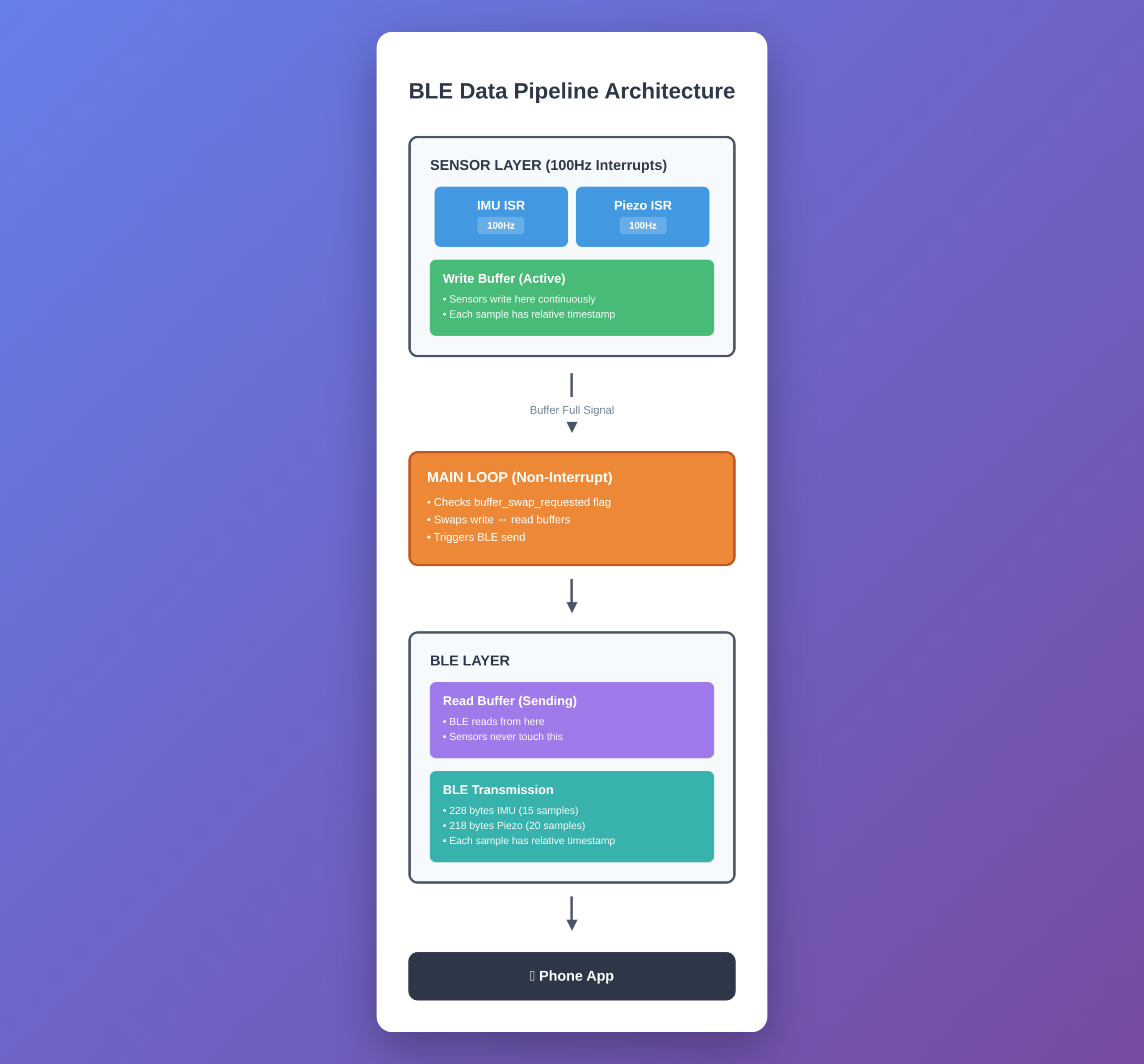
Dual Buffer Solution
To handle sensor and BLE callbacks running at the same time, we used dual buffering:
How it works:
- Two buffers per sensor (Buffer A and Buffer B)
- Sensor callback always writes to “write buffer”
- BLE callback always reads from “read buffer”
- When write buffer fills up, we swap the pointers
- Swap happens in main loop, not in interrupts
The key rules:
- Sensor callback: Always writes to write_buffer, never blocks
- BLE callback: Always reads from read_buffer, never interferes with sensors
- Buffer swap: Only happens when BLE is ready, outside of interrupt context
- No locks needed: Just one flag and atomic pointer swap
Why Dual Buffer Matters
Without dual buffering, we had these issues:
Problem 1: BLE callback blocks for 20-50ms while transmitting
- During this time, 2-5 sensor readings happen
- If sensor writes to same buffer, data gets corrupted
Problem 2: Sensor callback can’t wait
- It fires every 10ms exactly
- If it has to wait for BLE to finish, we lose timing accuracy
- Missing even one callback means 100Hz becomes 99Hz
Problem 3: Race conditions
- Sensor writes sample #47
- BLE reads sample #47 at same moment
- BLE gets half old data, half new data
- Corrupt samples ruin heart rate analysis
Dual buffering solved all of this. Sensor callback and BLE callback never touch the same memory.
Watchdog Timer Management
The watchdog timer was critical for field reliability (catching firmware crashes), but it caused problems during BLE operations.
The Watchdog Problem
We set a 5-second watchdog timeout. But:
- BLE connection can take 8-10 seconds in bad signal conditions
- Sending large buffered data after reconnect takes 6-8 seconds
- OTA firmware updates take 30+ seconds
All of these would trigger the watchdog and reset the device mid-operation.
Selective Watchdog Strategy
We managed the watchdog based on what operation was happening:
Normal operation: 5-second timeout (catch real crashes) BLE connecting: Disabled (connection time is unpredictable) Large data sends: 15-second timeout (allow time but still protect against hangs) OTA updates: Disabled (updates can take minutes)
This approach:
- Keeps watchdog active during normal operation
- Disables it during unpredictable operations
- Extends timeout for slow but predictable operations
- Always re-enables after the operation completes
Final Architecture: How It All Works Together
Key Lessons on BLE Data Structures
-
Timestamp Strategy Matters More Than You Think
-
- We tested: absolute every sample, relative every sample, first+last only
- We used relative timestamps (2 bytes per sample) for proof of each reading at 100Hz
- First+last timestamp method is better for bandwidth (saves 22 bytes per packet)
- Choose based on your needs: individual proof vs bandwidth savings
-
Callbacks Need Careful Isolation
-
- Never let BLE callbacks block sensor callbacks
- Never let sensor callbacks wait for BLE
- Dual buffers completely separate the two processes
- Buffer swap happens outside interrupts
-
BLE Connection is a Critical State
-
- Must pause sensor callbacks during connection
- Must disable or extend watchdog timeout
- Must sync timestamps with phone immediately after connection
- Better to lose 500ms of data than corrupt the whole buffer
-
Watchdog Management is Not Optional
-
- Field devices will crash (EMI, bugs)
- But watchdog can’t interfere with legitimate slow operations
- Use state-based watchdog timeouts
- Always re-enable after special operations
-
Design for Real BLE Behaviour
-
- Connection can take 10+ seconds in bad conditions
- MTU can downgrade randomly (247 → 23 bytes)
- Packets can be delayed or lost
- Structure must handle all this.
Results
This architecture is stable and has been running on a few collars for a few weeks now as we are still in a development phase.
Questions about BLE buffer management or high-frequency sensor data? Reach out to Oxeltech