Table of Content
ToggleMTBF as a Failure Time Frequency Prediction Criteria
From play gadgets to professional machines, it is relevant for the product sellers as well as regulatory authorities and consumers to know the probability of failures expected in the lifetime of the device. In electronics, one metric often used to estimate device performance over its lifetime is MTBF.
Mean Time Between Failure (MTBF) is the average time between the failures of pieces of a given product.
The MTBF of a device and its failure rate have an inverse relationship:
MTBF = 1/λ
The units in this case are hours or lifecycles. It also allows for the calculation of one of the other quantity is known. For this particular analysis, the conventional bath-tub curve is used, specifically the central part of the curve.
In this part, the device has passed the initial failure risks and the rate at which devices fail becomes relatively constant. Assuming a constant failure rate, the probability that a device will work for a specific amount of time can be found by using the following relation:
Survival Probability of a Device = e-t/MTBF
Here t is the time in hours for which the survival probability of a device is to be found and MBTF is the cumulative value of the individual MTBF values of the components used in the device.
MTBF value prediction is a crucial part of product design and is used by reliability engineers and designers at different stages of the design process. There are various standards in place for implementing MTBF prediction and their selection is based on the particular design stage.
These standards and methods include MIL-HDBK-217F, Telcordia SR332, Siemens Norm, FIDES, and UTE 80-810 (RDF2000), etc. For the purpose of this document, MIL-HDBK-217F is discussed and two of its major prediction methods are explained briefly.
MIL-HDBK-217F Standard
MIL-217F is a standard that provides failure rate prediction models for electrical and mechanical component categories. All of this information related to the MIL-217F standard is given in the MIL-HDBK-217F handbook published by the United States Department of Defense.
There are two methods that are listed under this standard i.e. Part Count Method and Part Stress Analysis Method.
Reliability Prediction Methods in MIL-HDBK-217F Standard
MIL-217-F (Part Count Method)
In this prediction method, the quantity of parts, quality factor and environment settings and make a failure rate prediction.
As it factors in very few variables, its application is limited to the early stages of the design when the product is being proposed. The relation that is used for calculation is given here:
λ = Σi=1 to n Ni . λi . ΠQi
Here n is the total number of categories, Ni is the number of ith part, λi is the failure rate of the ith component and ΠQi is the quality factor. This relation equals to λ which represents the total failure rate of the device.
MIL-217-F (Part Stress Analysis Method)
As compared to the Part Count method, the Part Stress Analysis method includes more factors as compared to the part count method.
This makes this a much more accurate measure of failure rate. The model used for the part stress analysis method for microelectronic circuits and memories is shown here:
λp = ( C1ΠT + C2ΠE + λcyc ) . ΠQΠL
In this model, C1 is the failure rate of die complexity, ΠT is the temperature factor, C2 is the failure rate of the package, ΠE is the environment factor, λcyc is the failure rate induced by Read/Write cycles, ΠQ is the quality factor and ΠL is the learning factor.
Software Solutions for Failure Rate and MTBF Calculation
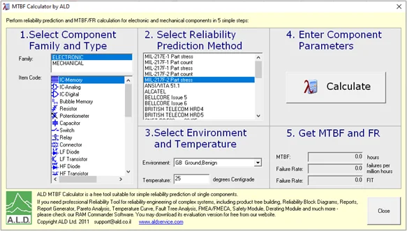
In addition to the manual failure rate calculation by using the MIL-HDBK-217F standard handbook, there are software tools as well that are available online for free. One of the simplest tools that can be used for failure rate value calculation is provided by ALD services. The software supports both the part count method and the part stress analysis method. This can be illustrated by the figure below in which the main window is shown:

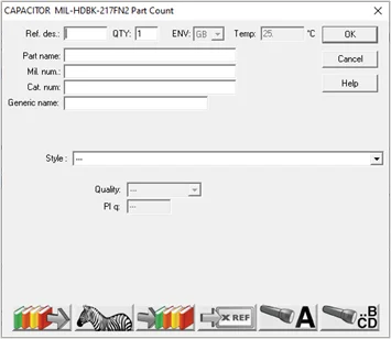
As observed in the figure, both variants of MIL-217F i.e. part count and part stress analysis, are available. To develop a comparison between the details used in both methods, their corresponding dialogue boxes can be compared. Here is the snapshot of the dialogue box for the part count method for a capacitor in which the main factors are quantity, part number, and style, etc.

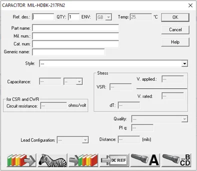
In contrast to the part count method, the part stress analysis takes into account quantity, part number, style, value, rated and applied voltage, quality, termination style and in-circuit resistance etc. This can be clearly visualized in the following snapshot:

The software can be downloaded from the link [1] given in the ‘Useful Links’ section and further explored. Furthermore, another MTBF calculator available at Digikey’s website can also be used for failure rate calculation.
To conclude, we have looked at the core idea behind the terms ‘’Mean Time between Failures’ and failure rates, and the methods used to calculate them. We have also covered online tools that can be utilized to calculate these quantities.
Useful Links
If you are facing any difficulties with your MTBF Analysis, or other Reliability Analysis of your design or product, or any design-related challenge in general, feel free to Contact Us for our consultancy. You can check out our other Technical Blogs on various topics or visit our new website Oxeltech.de to find all about our services and products.


