This blog is a guide to help you interface an IMU sensor such as LIS3DSH with a Bluetooth-enabled microcontroller such as NRF52 from Nordic, and use Zephyr OS to accomplish that. The blog will also help you understand establishing SPI communication using Zephyr OS.
For interfacing our MEMS IMU sensor LIS3DSH with NRF52, we’ll be using the NRF Connect SDK that comes bundled up with the Zephyr Operating system.
NRF52 can also be used with the older NRF5 SDK but in doing so you won’t be able to use Zephyr OS out of the box. You do have the option of using FreeRTOS with NRF5 SDK, however, you will still miss out on the adaptability aspect of the Zephyr OS and its device drivers which are supported across much different hardware.
For more info about NRF connect SDK, do refer to the Nordic Developer’s academy’s getting started guide on NRF Connect SDK.
Table of Content
ToggleA bit about the Zephyr Project
The main highlight of the NRF Connect SDK is that it’s embedded with the Zephyr operating system. The Zephyr Project is a scalable real-time operating system (RTOS) supporting multiple hardware architectures, optimized for resource-constrained devices.
The Zephyr RTOS is a Linux Foundation-hosted open-source collaboration project. It is based on a small-footprint kernel designed for use on resource-constrained systems: from simple embedded environmental sensors and LED wearables to sophisticated smart watches and IoT wireless gateways.
Zephyr supports more than 350 boards; the complete list can be found here. This diversity of supported boards gives developers and product manufacturers multiple options to solve their embedded RTOS challenges with Zephyr. If your board is not supported out of the box, adding support for a new board is simple.
Zephyr works in a similar way like a Linux kernel based on CMAKE. The Zephyr build process can be divided into two main phases: a configuration phase (driven by CMake) and a build phase (driven by Make or Ninja).
The configuration phase mainly relies on the deviceTree files, collected from the target’s architecture, SoC, board, and application directories.
These files describe the hardware structure in form of nodes and can be accessed by use in the main code. For more information about Zephyr’s build and configuration system refer to the Zephyr Project documentations.
The SPI Interface
SPI is one of the serial communication protocols developed by Motorola. It stands for Serial Peripheral Interface and is a popular communication protocol in embedded systems.
SPI involves a master device and a slave device. The master device controls the communication, e.g., it decides when to request data from the slave. The protocol uses 4 wires which are named SCK (serial clock), MISO (master in slave out), MOSI (master out slave in) and CS (chip select).
Due to its popularity, most microcontrollers, including nRF52, have hardware blocks supporting this protocol so that you don’t need to manually control these signals from your code.
NRF52 has two modules implementing SPI communication: the SPI and SPIM peripherals. The only difference between SPI and SPIM is that SPIM uses a special hardware module called EasyDMA which uses regions of RAM to speed up the reading and writing process from the transfer and receiver buffers.
There are 3 instances of SPI available referred as SPI0, SPI1 and SPI2 and similarly 3 instances for SPIM. Each of the SPI instances supports a maximum frequency as in the case of NRF52832, it’s 8Mhz
For SPI communication, you can choose any GPIO pins for CS, MOSI, MISO and SCK can be configured through our code.
SPI is a full duplex form of communication that means once a master device as in our case NRF52 will send a byte through MOSI (master out slave in) pin and so at the same time slave also transmits a byte of data from the MISO (Master in slave out) pin.
The connection between our Master device (NRF52) and our Sensor (Slave) will be as follows. Unlike UART communication we do not cross out MOSI and MISO connection pins.
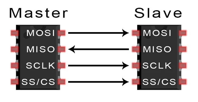
Using this kind of Master – slave connection ensures that a Master (Microcontroller) can be interfaced with multiple sensors (slaves) on the same lines and can dynamically select which sensor to get values (information) from at runtime. For more information on SPI protocol refer to this article attached
About LIS3DSH
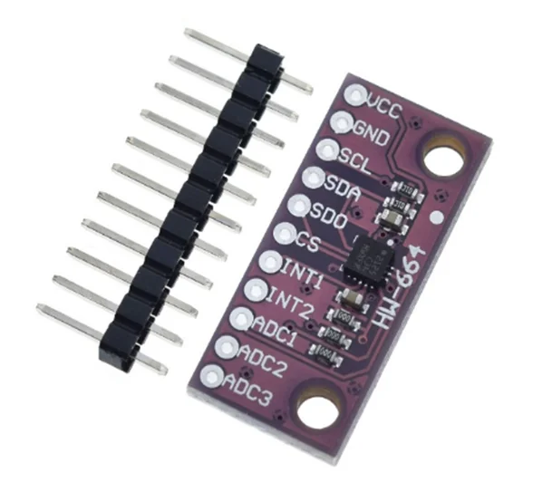
The sensor that we’re going to use for interfacing over SPI is LIS3DSH. The LIS3DSH is an ultra-low-power high performance 3-axis linear accelerometer. It is capable of measuring accelerations with output data rates from 3.125 Hz to 1.6 kHz.
It can be interfaced on SPI or I2C protocols. For our case we’ll be interfacing over SPI. To get started with this sensor, use the pin headers to mount this on a breadboard and solder the headers on to the sensor board.
Getting started
To get started with the interfacing LIS3DSH sensor with the NRF52 development kit. Make sure you have NRF connect sdk setup. We’ll use Zephyr’s SPI drivers to connect with our sensor.
This ensures the adaptability of our code to other development boards, as our solution for interfacing with NRF52 using Zephyr OS would make our application portable, meaning that using the same source code we can interface this sensor with any other development board running Zephyr OS or NRF Connect SDK.
To begin, setup wiring connections as shown in the table. VCC pin of LIS3DSH will be connected to the VDD pin on NRF52 which provides 3.3 volts. GND can be connected with any of the Ground pin of NRF52DK.
For our demo, we’ll only require using the SCL, SDA, SD0 and CS pin on the LIS3DSH. We can use any GPIO pins for SCL, SDA, SD0 and CS from NRF52 and can be specified in the Device Overlay file (more on that later).
For now, we’ll connect our pins as follows
| LIS3DSH pin | NRF52 GPIO pin |
|---|---|
| SCL/SCK | 31 |
| SD0 (MOSI) | 30 |
| SDA (MISO) | 29 |
| CS (SS) | 17 |
To get started with writing code for interfacing, open your VS Code, If the NCS is correctly configured then it will show this welcome page from NRF Connect SDK.
Proceed to “Create a new Application” and select the installed sdk version along with tool chain and application folder. From the Application template, you may select the “Blinky” and give it an application name suitable for our project.
You will be presented with a main.c along with a VScode workspace (by clicking on the explorer button in the side bar) with all your project files as shown.
Next up, we’ll modify the prj.conf file to enable the GPIO as well as SPI drivers. Open the prj.conf file and paste the following lines.
CONFIG_GPIO=y

CONFIG_SPI=y

CONFIG_SPI_ASYNC=y
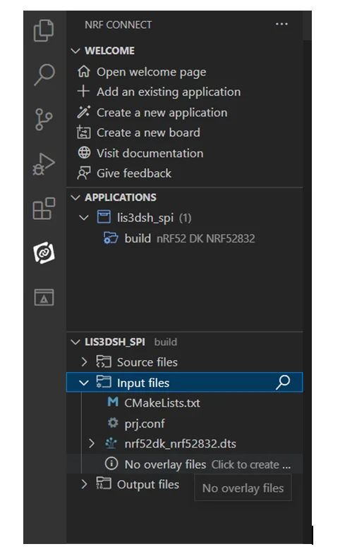
Now, we’ll modify the DeviceTree by creating it’s overlay. For that click on the nRF connect extension symbol in the left-sidebar (second last one).
Under Applications click on the Add build configurations options. Here you should select your development board, for me it’s nrf52dk_nrf52832 and click on Build Configurations.
Now in the sidebar you’ll be able to see foldersfor source files, input and output files. Expand the input files option and click on the “No overlay files click to create one” option.
Using Zephyr for Interfacing LIS3DH
Now open the overlay file just created and paste the following code
<pre class="EnlighterJSRAW" data-enlighter-language="generic" data-enlighter-theme="" data-enlighter-highlight="" data-enlighter-linenumbers="" data-enlighter-lineoffset="" data-enlighter-title="" data-enlighter-group="">&pinctrl {
spi1_default: spi1_default {
group1 {
psels = <NRF_PSEL(SPIM_SCK, 0, 31)>,
<NRF_PSEL(SPIM_MOSI, 0, 30)>,
<NRF_PSEL(SPIM_MISO, 0, 29)>;
};
};
spi1_sleep: spi1_sleep {
group1 {
psels = <NRF_PSEL(SPIM_SCK, 0, 31)>,
<NRF_PSEL(SPIM_MOSI, 0, 30)>,
<NRF_PSEL(SPIM_MISO, 0, 29)>;
low-power-enable;
};
};
};
&spi1 {
compatible = "nordic,nrf-spi";
status = "okay";
pinctrl-0 = <&spi1_default>;
pinctrl-1 = <&spi1_sleep>;
cs-gpios = <&gpio0 17 GPIO_ACTIVE_LOW>;
};</pre>This will import the SPI1 instance from the DeviceTree and specifies the pins to use for SCK, MOSI and MISO as well as the GPIO pin to be used for cs-gpios. Once this is done, head back to the main.c file to start the configuration process of the SPI module.
Main code to configure SPI and interface with LIS3DSH
#defineSPI_BUFSIZE  8   //SPI Communication buffer size
uint8_t   spi_tx_buf[SPI_BUFSIZE]; // spitx buffer
uint8_t   spi_rx_buf[SPI_BUFSIZE]; // spirx buffer
First, we’ll define the buffer size of our transfer and receive buffers and define two arrays one for transmitting and another one for receiving.
#defineADD_REG_WHO_AM_I                0x0F
#defineUC_WHO_AM_I_DEFAULT_VALUE       0x3F
/* set read single command. Attention: command must be 0x3F at most */
#defineSET_READ_SINGLE_CMD(x)         (x |0x80)
Here we define two macros, the Address of a WHO AM I Register and its value. This is a register inside the LIS3DSH, and it contains a fixed value used to authenticate if communication is established between the microcontroller and the sensor. This can be found in the datasheet of LIS3DSH.
We also define another macro that takes an input “x” and performs an OR operation with 0x80 and returns the value. This is a standard operation found in the datasheet, performed on an address of the register present inside LIS3DSH to convert it into a command that returns the content of that register.
Since SPI is full-duplex communication, each time one byte of data is transmitted to the sensor via the MOSI line and the sensor also at the same time sends a byte of data back to Microcontroller.
Similarly in this case we transmit a command from the tx buffer at spi_tx_buf[0] and at the same time without processing the command send at the tx buffer, LIS3DSH returns an arbitrary value at the spi_rx_buf[0].
After this the sensor returns the contents of the WHO AM I register at the spi_rx_buf[1]. Once we receive the correct value from the buffer, we can be sure that the spi is set up to begin communication with the sensor. Our task for now, is to ensure that SPI communication is correctly set up.
conststructdevice *spi_dev = DEVICE_DT_GET(DT_NODELABEL(spi1)) ;
    if(!device_is_ready(spi_dev)) {
        /* Device is not ready to use */
        printk("rnStop device not readyrn");
    }
Inside our void main, we first get the spi instance from the deviceTree, in this case we’re using the spi1. We then check if the spi device is ready.
structspi_cs_control chip =
    {
        .gpio_dev = DEVICE_DT_GET(DT_NODELABEL(gpio0)),
        .gpio_pin = 17,
        .gpio_dt_flags = GPIO_ACTIVE_LOW,
        .delay = 2
    };
We then define a SPI chip select structure for our slave device and assign gpio pin 17 at which we’ll connect with the SS pin of our sensor.
structspi_configspi_cfg = {
                .frequency = 4000000,
                .operation = SPI_WORD_SET(8) | SPI_TRANSFER_MSB |
                 SPI_MODE_CPOL | SPI_MODE_CPHA,
                .slave = 0,
                .cs = &chip
    };
Next, we declare a spi configuration structure and set the frequency to 4MHz and also assign the chip select to the spi cs control structure declared above.
structspi_buftx_buf_arr = {.buf = spi_tx_buf, .len=8};
    structspi_buf_settx = {.buffers = &tx_buf_arr, .count = 1};
Then we declare a spi buffer structure and assign our spi_tx_buf array to the .bufparameter along with the buffer size as the .len parameter. This structure is passed as a reference to the spi_buf_set structure and since we’re only using one instance of the spi_buf structure so we assign the count as 1.
structspi_bufrx_buf_arr = {.buf = spi_rx_buf, .len = 8};
    structspi_buf_setrx  = {.buffers = &rx_buf_arr, .count = 1};
And similarly, we do the same for the receiver buffers.
    spi_tx_buf[0] = SET_READ_SINGLE_CMD(ADD_REG_WHO_AM_I);
    int error = spi_transceive(spi_dev,&spi_cfg,&tx,&rx);
    if(error != 0){
        printk("SPI transceive error: %in", error);
    }
Here we set the 0thindex of our transfer buffer with the command to address the WHO AM I register(specific to LIS3DSH) and we use the spi_transceivefor the communication process.
According to our code, we specified the command on 0th index of the transfer buffer which means that the value of the register pointed by the transfer bufferspi_tx_buf[0] will be returned on the 1th index of thespi_rx_buf.
We can ignore the value received at thespi_rx_buf[0] as it’s not relevant to us and check if the value received is same as the WHO AM I register specified in the datasheet of the LIS3DSH.
if (spi_rx_buf[1] == UC_WHO_AM_I_DEFAULT_VALUE)
    {
        printk("LIS3DSH detected rn");
    }
Once we build and flash the code, we can open up a UART terminal, in our case Putty terminal and check that LIS3DSH was indeed detected.

Once we’ve ensured that our SPI communication is all set up, then we can move to receive the actual values of accelerations in x, y and z axis. For that we’ve attached below a github link to the library that can handle all the addressing of the individual registers present in the LIS3DSH that return the value for the accelerations for us.
The code shared above for configuration of SPI module and authentication of the sensor can be found at the link: NRF52 – SPI – NCS git
Using the LIS3DSH library
In order to use this library, you’ll have to include the LIS3DSH.h file in the main.c. Make sure you place the .h and .c file in the srcfolder of the workspace shown in VScode. Next, we’ll add a command to CMAKELIST.txt file to ensure that our specified library file is included during the build process.
Open the CMAKELISTS.txt file and paste the following line
target_sources(app PRIVATE src/lis3dsh.c)
In our void main we’ll just have to call the SPI_init() function from our lis3dsh library and it will handle the spi initialization process as well as the authentication of the LIS3DSH sensor as we demonstrated above.
Along with that it also configures the LIS3DSH sensor’s output rate as well as enable the accelerometer’s enable for x,y and z axis. It uses anLIS3DSH_write_regfunction that passes configuration values for LIS3DSH sensor.
void main(void)
{
    //Call the SPI initialization function
    SPI_Init();
    intacc_x, acc_y, acc_z ;
    //values that hold the values of acceleration in mg
    while(true)
      {
        get_acceleration(&acc_x,&acc_y,&acc_z);
        printk("X= %6dmg Y= %6dmg Z= %6dmg rn", acc_x, acc_y, acc_z);
        k_msleep(300);
      }
}
In our while forever loop, we’ll just pass a reference to our 3-axis variables and the get_acceleration() function from the lis3dsh library will copy the acceleration values onto our passed variables and can be displayed on a UART terminal with units of mg. which is 1/1000 of a g where the value of g is the acceleration of gravity 9.81
Inside the LIS3DSH sensor, the values for the accelerations in three axes are stored separately in registers. Each acceleration value e.g. in the x-axis is stored in two parts, the higher byte(OUT_X_L), and the lower byte (OUT_X_H). This is done by passing the address of this register in terms of a command (specified in the .h file of library) to the LIS3DSH_read_reg function.
Inside the LIS3DSH_read_reg function we see that to read from any register we just specify the address of that register to the macro SET_READ_SINGLE_CMDwhich converts it into a command and copying that on to the 0th index of the transfer buffer.
In case we want to write to an internal register, we use the LIS3DSH_write_reg function. Inside of this function we specify the address of the register that we want to write to and convert it into a command by passing it through the macro SET_WRITE_SINGLE_CMDand copying that to the 0th instance of the transfer buffer. Since we’re writing to the register, we specify the data that we want to write on the 1st instance of the transfer buffer.
The values of acceleration that we receive from the LIS3DSH_read_regfunctionis in the 2’s complement form, hence it’s converted in to the 16-bit integer value by the function twoComplToInt16.
In the library’s header file, we can find different macro definitions mostly for the addresses of the internal register of LIS3DSH (can be found in the datasheet) along with a few macro functions that do simple conversions from addresses to read/write commands.
For more information on how to set up SPI communication on Zephyr on how to use the LIS3DSH, feel free to reach out to Oxeltech.
Also read: How to Write Driver for Accelerometer LIS3DSH in Zephyr
Links to our GitHub Repositories:
- Basic interfacing: NRF52 – SPI – NCS git
- Using the LIS3DSH library: NRF52-LIS3DSH Git
References:
- https://zephyrproject.org/
- https://github.com/zephyrproject-rtos/zephyr
- https://docs.zephyrproject.org/3.0.0/guides/build/index.html
- https://embeddedexplorer.com/nrf52-spi-tutorial/
- https://academy.nordicsemi.com/courses/nrf-connect-sdk-fundamentals/
- https://github.com/too1/ncs-spi-master-slave-example
- nRF5 SDK – Tutorial for Beginners Pt 36 B – SPI Communication with LIS3DSH Sensor
- https://www.circuitbasics.com/basics-of-the-spi-communication-protocol/
- https://www.st.com/resource/en/datasheet/lis3dhh.pdf


