This case study demonstrates how a precision 16-channel Class AA RTD PT100 temperature measurement system achieves ±0.1°C accuracy at 0°C. By combining Class AA sensors (DIN EN 60751) with ratiometric measurement architecture and proper component selection, the system provides laboratory-grade accuracy suitable for pharmaceutical, medical device, and precision industrial applications.
1. System Requirements and Design Philosophy
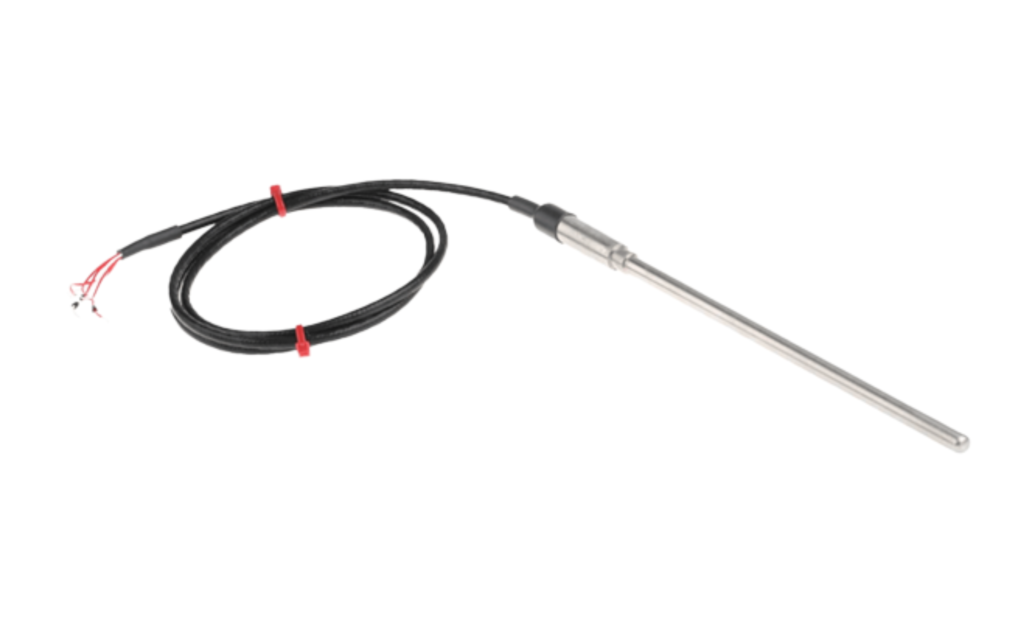
1.1 How PT100 Sensors Work
An RTD (like PT100) is a resistance temperature detector. It is a temperature sensor that uses the change in electrical resistance of a metal element to infer temperature. The resistance increases or decreases in a repeatable pattern as the element warms or cools. Platinum RTDs like PT100 and PT1000 are common because platinum has a stable, well-characterized resistance-temperature relationship and follows international standards such as DIN EN 60751.
The measurement system does not measure temperature directly. It forces a small current through the RTD, measures the resulting voltage, computes resistance, then converts that resistance to temperature using the standard equation. Errors in resistance measurement map linearly to temperature errors, which is why wiring resistance, current stability, and reference accuracy matter.
1.2 Application Requirements That We Had
- Primary Use: Pharmaceutical validation and medical device manufacturing
- Critical Temperature: 37°C (body temperature reference point)
- Accuracy Target: ±0.2°C at 37°C
- Channels: 16 independent measurement points
- Compliance: DIN EN 60751
1.3 Why Ratiometric Measurement?
Traditional Approach:
- Uses constant current source to excite PT100
- Measures voltage drop across sensor
- Problem: Current source accuracy directly affects temperature measurement
- Example: 1% current error causes ±2.5°C temperature error
Ratiometric Approach:
- Measures the ratio: V_PT100 / V_Reference
- Excitation current appears in both measurements
- Advantage: Current cancels out in the ratio calculation
- Only reference resistor accuracy matters
- Result: Eliminates dependency on current source precision
This fundamental design choice enables high accuracy with simpler, more cost-effective circuitry.
2. Key Design Elements for Class AA Accuracy
2.1 Class AA PT100 Sensors
DIN EN 60751 Class AA Specification:
Tolerance = ±(0.1 + 0.0017 × |T|)°C
Practical accuracy at key temperatures:
- At 0°C: ±0.10°C
- At 37°C: ±0.162°C
- At 100°C: ±0.27°C
Why Class AA is essential:
- Provides the tightest tolerance available in standard PT100 sensors
- 1.5× better than Class A sensors
- 3× better than Class B sensors
- Required baseline for achieving ±0.2°C system accuracy
2.2 Four-Wire Connection (Mandatory)
Connection methods compared:
2-Wire: Simplest wiring, but lead resistance adds directly to measurement
- Error: ±1-2°C typical (unusable for precision)
3-Wire: Partially compensates for lead resistance
- Error: ±0.1-0.2°C (requires matched lead resistance)
4-Wire: Complete elimination of lead resistance error
- Separate current excitation leads (I+, I-)
- Separate voltage sensing leads (V+, V-)
- High-impedance voltage measurement
- Error: <±0.01°C (essential for Class AA accuracy)
Implementation: The four-wire configuration is non-negotiable for achieving ±0.2°C accuracy targets.
2.3 Precision Reference Resistor – The Critical Component
In ratiometric measurement, the reference resistor is the most important component affecting accuracy.
PT100 Resistance Calculation
The resistance of a PT100 sensor at temperature (°C) is given by the IEC 60751 Callendar–Van Dusen equation for T ≥ 0 °C:
R(T) = R₀ (1 + AT + BT²)
Where:
R₀ = 100 Ω
A = 3.9083 × 10⁻³
B = −5.775 × 10⁻⁷
Example at 37 °C:
R(37) = 100 × (1 + 3.9083 × 10⁻³ × 37 − 5.775 × 10⁻⁷ × 37²) ≈ 114.3817 Ω
PT100 Accuracy (DIN EN 60751 Class AA)
Class AA tolerance:
Tolerance = ±(0.1 + 0.0017 × |T|) °C
| Temperature | Tolerance (°C) |
| 0 °C | ±0.10 |
| 37 °C | ±0.162 |
| 100 °C | ±0.27 |
Corresponding resistances:
T = 37 + 0.1629°C → R ≈ 114.4446 Ω
T = 37 − 0.1629°C → R ≈ 114.3187 Ω
Reference Resistor
The system uses a 2 kΩ reference resistor with ±0.01% tolerance:
RREF = 2000 ± 0.2 Ω (1999.8 Ω to 2000.2 Ω)
Voltage Drops with 1 mA Excitation Current:
| Case | V_REF | V_PT100 | Notes |
| Ideal | 2.0000 V | 114.3817 mV | Converts exactly to 37 °C |
| Max | 1.9998 V | 114.4446 mV | Converts to 37.193 °C |
| Min | 2.0002 V | 114.3187 mV | Converts to 36.808 °C |
System accuracy at 37 °C: 37 ± 0.19°C
How the Ratiometric Measurement Works
The PT100 resistance is measured ratiometrically:
RPT100 = (VPT100 / VREF) × RREF
- The excitation current cancels out.
- Any tolerance in produces an equal percentage error in the measured PT100 resistance:
ΔRPT100 / RPT100 = ΔRREF / RREF
The resulting temperature error is obtained by dividing the resistance error by the PT100 sensitivity (0.385 Ω/°C):
ΔT = ΔRPT100 / 0.385
Example at 37 °C (R ≈ 114.38 Ω):
- 0.01% reference resistor tolerance →
ΔR = 0.0001 × 114.38 = 0.0114 Ω
ΔT = 0.0114 / 0.385 ≈ ±0.029°C
Therefore, 0.01% thin-film or bulk-metal-foil resistors are necessary to achieve Class AA ±0.2 °C accuracy.
Impact of Reference Resistor Tolerance at 37 °C
| Reference Tolerance | Temperature Error at 37 °C | System Accuracy |
| 1% (±20 Ω) | ±2.97 °C | ±3.13 °C |
| 0.1% (±2 Ω) | ±0.297 °C | ±0.45 °C |
| 0.01% (±0.2 Ω) | ±0.0297 °C | ±0.19°C |
Key insight: The reference resistor dominates system accuracy. Using a standard 1% resistor makes ±0.2 °C accuracy impossible, regardless of PT100 quality or circuitry.
Required specification for Class AA systems:
- Tolerance: 0.01% or better
- Technology: Thin-film or bulk metal foil
2.4 High-Resolution Analog-to-Digital Converter
- 16-bit resolution provides 0.0015°C per bit – sufficient for ±0.2°C system accuracy requirement
- Ratiometric measurement support: Differential inputs measure V_PT100 / V_REF ratio
- Burnout current detection: Identifies open/short sensor faults for system reliability
2.5 Low-Drift Voltage Reference
- Importance: Reference accuracy directly determines system accuracy – 0.1% reference error causes ±0.25°C temperature error
- Required specifications: ±0.05% initial accuracy, <10 ppm/°C temperature coefficient
2.6 Analog Multiplexers
- Low on-resistance (<10Ω) and low leakage (<1 nA) for accurate 4-wire measurements
- Critical settling time: Must wait 5-10 ms after switching to prevent ±0.5-2°C errors
2.7 Standard Resistors in Circuit
Non-critical resistors (1-5% tolerance acceptable):
- Input protection resistors (not in measurement path)
- EMI filtering resistors (only affects time constant, not accuracy)
- Pull-up and pull-down resistors (digital/logic functions)
- Current source setting resistors (ratiometric measurement makes current accuracy irrelevant)
Why standard tolerance is acceptable: These resistors are either outside the precision measurement path, or their errors cancel in the ratiometric calculation.
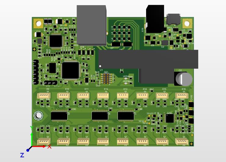
3. System Architecture
3.1 Signal Chain Overview
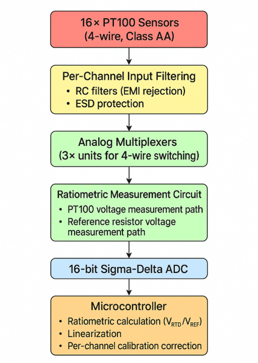
3.2 Measurement Sequence
For each channel (sequential scanning):
- Select Channel: Digital control switches multiplexers to channel N
- Settling Delay: Wait 5-10 ms (critical for accuracy)
- Measure Reference: ADC reads voltage across reference resistor
- Measure PT100: ADC reads voltage across PT100 sensor
- Calculate Ratio: V_PT100 / V_Reference (current cancels)
- Apply Calibration: Use stored gain and offset coefficients
- Linearize: Convert resistance to temperature
- Output Temperature: Digital value
Complete cycle: All 16 channels measured in ~1 second (1 Hz update rate)
4. Implementation Best Practices
4.1 PCB Layout Guidelines
Grounding strategy:
- Implement star ground topology
- Single connection point between analog and digital grounds
- Minimize ground loops in precision measurement path
Component placement:
- Position precision reference resistor in thermally stable area
- Keep away from heat-generating components (voltage regulators, power devices)
- Minimize thermal gradients across critical components
- Use thermal relief on precision component pads
Signal routing:
- Route 4-wire RTD connections as differential pairs
- Guard sensitive high-impedance traces
- Minimize trace lengths for voltage sensing
- Use ground planes with proper stitching
Filtering implementation:
- Per-channel RC filtering at inputs
- Multiple filter stages on voltage reference
- Combination of ceramic and film capacitors for broad frequency rejection
Conclusion
Our developed 16-channel PT100 measurement system demonstrates that ±0.19°C accuracy at 37°C is achievable through:
- Class AA PT100 sensor: ±0.19°C at 37°C (largest single contributor)
- 0.01% reference resistor: ±0.025°C (critical enabler)
- 4-wire connection: Eliminates ±1-2°C lead resistance error
- Proper settling time: Prevents ±0.5-2°C switching transients
- Per-channel calibration: Reduces residual errors
The system provides laboratory-grade ±0.19°C (exceeds ±0.2°C requirement) accuracy suitable for FDA-regulated pharmaceutical validation and medical device manufacturing, while maintaining the practical benefits of a 16-channel multiplexed architecture with 1 Hz update rate across all channels.
The key to success: Understanding that achieving Class AA system accuracy requires not just Class AA sensors, but a complete measurement chain designed to preserve (and not degrade) the sensor’s inherent precision.
If you need support designing sensor based hardware or programming embedded firmware, reach out to the Oxeltech team.