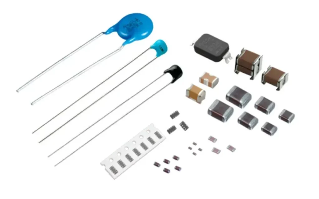
Ceramic Capacitors or multilayer ceramic capacitors (MLCC) are the most commonly used type of capacitors now a days. This fame can be attributed to their low cost and small size. But there are other factors that are important to consider when you choose capacitors in your circuit design. The most important ones are listed below.
CV Rating of the Capacitor
For designing space-constrained boards, capacitors offering higher capacitance as well as higher voltage in small size are valuable for space saving.
The CV rating reflects the volumetric efficiency of a capacitor and its chemistry. In general, the higher the capacitance, the larger the volume of the capacitor. And given some capacitance value, the higher the voltage rating, the larger the volume of the capacitor. So when a capacitor has a “high CV rating”, that means that it is volumetrically efficient, and offers a small physical size compared to other capacitor types.
Reference: https://www.physicsforums.com/threads/cv-rating-of-a-capacitor.269285/
Among the capacitor types of film capacitors, ceramic capacitors, aluminum electrolytic and aluminum polymer, ceramic capacitors offer the best CV rating. Even within ceramic capacitors, different products could offer varying CV rating. You may need to pay a bit more for higher CV rating ceramic capacitor.
ESR
ESR stands for Equivalent Series Resistance. It is a characteristic which has both pros and cons.
On one hand you’d like some series resistance because it damps the signal and makes the design of the control loop easier. If you completely eliminate ESR, you’ll have ringing.
On the other hand, increased ESR increases the ripple which is undesired e.g. in applications such as low pass filters. In low pass filter, in fact, ripple is what you’re primarily trying to reduce.
Read more on the topic of ESR in the articles below
- Relationship Between ESR, Loss Tangent, Dissipation Factor, and Q
- Methods and Problems of ESR measurements ++++
- Measure Capacitor ESR with an Oscilloscope and Function Generator
- http://www.low-esr.com
Among the different types of capacitors, ceramic capacitors come out to be low ESR but have the potential for ringing. Read more about the comparison of different capacitors from ESR and ringing point of view here
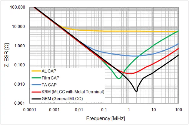
Figure 1: ESR vs Frequency of different capacitor types
Source: https://www.murata.com/en-eu/support/faqs/capacitor/ceramiccapacitor/char/0026
The right choice of capacitor isn’t lowest ESR, rather it is usually the one which gives a nice, flat impedance curve without resonances (AL and TA caps in the graph above). Ceramic capacitors, as evident from the photo above, has a sharp resonance frequency. So when using ceramic capacitors, this needs to be considered and ringing/resonance should be prevented by other means.
DC Bias Loss
High-capacity, multilayer ceramic capacitors (MLCC) have a property often not well understood by electronic designers: the capacitance of these devices reduced with increase in applied DC voltage.
The capacitor rating for ceramic capacitors is shown in the datasheet at 0V. The manufacturers measure the capacitance around the capacitor using an AC signal around 0V. If you increase the DC voltage on ceramic capacitors, the capacitance drops and that is called the DC bias loss.
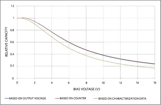
Figure 2. Relative capacity as a function of bias voltage for a 2.2µF/16V MLCC.
Image Credits: https://www.maximintegrated.com/en/design/technical-documents/tutorials/6/6014.html
This loss is particular to ceramic capacitors and other types of capacitors such as film capacitors and aluminum electrolytics capacitors do not suffer from this phenomenon.
Also See Application note 6014, “How to Measure Capacity Versus Bias Voltage on MLCCs.”
Temperature And Voltage Variation of Ceramic Capacitors
The most common capacitor in ceramic type you’ve heard is probably X7R.
Usually, the design engineers rely on the following table to decide which capacitors to use for their specific application
| 1st Character: Low Temp | Degree Celsius | 2nd Character: High Temp | Degree Celsius | 3rd Character: Change over Temp (max) | Tolerance in Capacitance |
| Z | +10 | 2 | +45 | A | ±1.0 |
| Y | -30 | 4 | +65 | B | ±1.5 |
| X | -55 | 5 | +85 | C | ±2.2 |
| – | – | 6 | +105 | D | ±3.3 |
| – | – | 7 | +125 | E | ±4.7 |
| – | – | 8 | +150 | F | ±7.5 |
| – | – | 9 | +200 | P | ±10 |
| – | – | – | – | R | ±15 |
| – | – | – | – | S | ±22 |
| – | – | – | – | T | +22, -33 |
| – | – | – | – | U | +22, -56 |
| – | – | – | – | V | +22, -82 |
But a closer look at capacitor data sheets will tell you that this is not the whole story. See the following graph
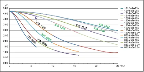
Figure 3. Temperature variation vs. DC voltage for select 4.7µF capacitors.
Image Credits: https://www.maximintegrated.com/en/app-notes/index.mvp/id/5527
It clearly shows that the value of capacitor depends not only on the tolerance given in its name (e.g. 15% for X7R) but also on the exact volts the capacitor faces.
You didn’t expect that, did you?
Here is a very comprehensive article by a Senior Principal Member of Technical Staff at Maxim Integrated, that covers this concept and others in detail.
Application Note 5527: Temperature And Voltage Variation Ceramic Capacitor
What are those COG (NPO) Type Ceramic Capacitors – Why Use them?
X7R, Y5V etc are so called Class II and Class III ceramic capacitors, however, COG (NPO) are Class I capacitors. Class I capacitors are more stable across environmental variations and do not exhibit piezo effects. That’s why COG (NPO) are recommended for circuits requiring low loss, circuits with pulse, timing circuits and tuning applications. The downside is that they are not as volumetrically efficient as X7R etc.
COG (NPO) type ceramic capacitors often have even lower ESR and can pose worse risks of resonance and ringing, but most of the applications such as low pass filters and decoupling etc, this type is considered an overkill anyway.
Conclusion
Ceramic capacitors offer high volumetric efficiency and are low cost, which are two important concerns for many applications now a days across different industries. However, there are no free lunches. Electronics Engineers need to be aware of the limitations of ceramic capacitors which include but aren’t limited to resonance/ringing due to low ESR and DC bias loss. With careful considerations in the design process, these limitations can be overcome.
Facing challenges with ceramic capacitor (MLCC) selection or electronic product development in general? Feel free to Contact Us for analog hardware design, embedded platform development, and firmware services.